A directional coupler and antenna

A directional coupler and antenna technology, applied in the field of communication, can solve the problems of large occupied space, difficult to meet the requirements of small size, large lateral size of the directional coupler, etc. The effect of size

Active Publication Date: 2016-11-30
HUAWEI TECH CO LTD
View PDF3 Cites 0 Cited by
  • Summary
  • Abstract
  • Description
  • Claims
  • Application Information

AI Technical Summary

Problems solved by technology

[0005] The embodiment of the present invention provides a directional coupler and an antenna, which solves the problem of the directional coupler caused by the increase in the size of the dielectric board and the floor when the microstrip circuit board adopts a matrix structure in the prior art. The horizontal size is large, the occupied space is large, and it is difficult to meet the technical problems of small size requirements

Method used


Image

  • A directional coupler and antenna
  • A directional coupler and antenna
  • A directional coupler and antenna

Examples


Embodiment 1

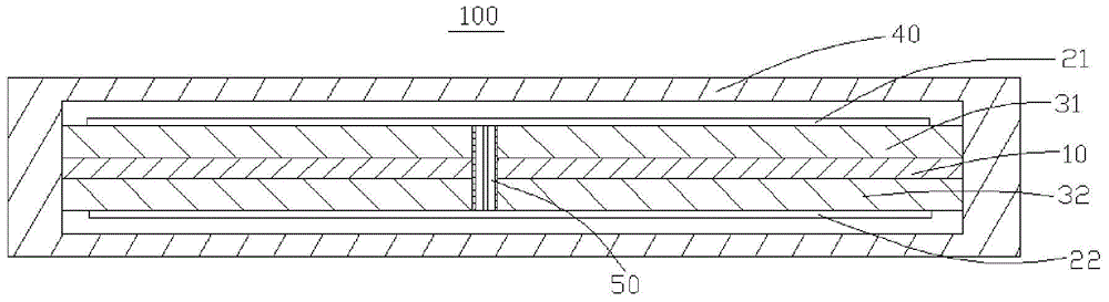
[0030] Such as figure 1 As shown, is a schematic cross-sectional view of the directional coupler 100 provided by the embodiment of the present invention. The directional coupler 100 can be used as a power divider for signal isolation, splitting and mixing. The directional coupler 100 includes a floor 10 , two microstrip circuit boards 21 , 22 and two dielectric boards 31 , 32 .

[0031] The floor 10 can be a metal plate, and a metal plate with better electrical conductivity can be selected, such as an aluminum plate, a copper plate, and the like.

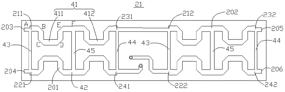
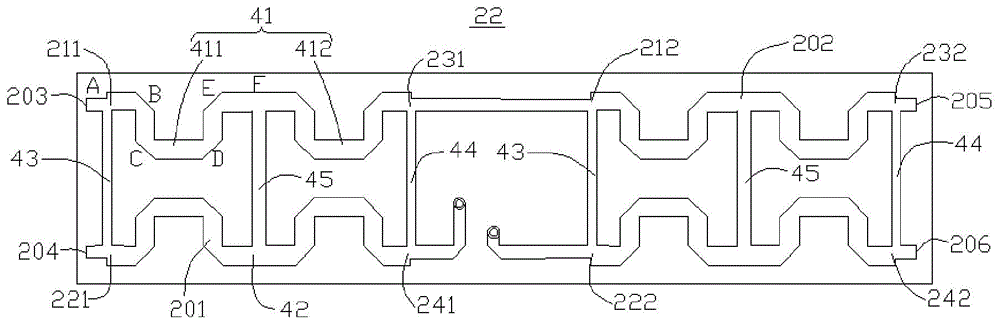
[0032] Please also see figure 2 with image 3 , the two microstrip circuit boards 21 and 22 are electrically connected to each other so as to be able to transmit signals to each other. Each of the two microstrip circuit boards 21 , 22 includes a first bridge 201 , a second bridge 202 , two input interfaces 203 , 204 and two output interfaces 205 , 206 . The first electric bridge 201 is electrically connected to the second elec...

Embodiment 2

[0050] Based on the same inventive concept, the present invention also provides an antenna 300, such as Image 6 As shown, it is a schematic diagram of the connection relationship of the antenna 300 provided by another embodiment of the present invention. The antenna 300 includes a directional coupler 320 and four columns of antenna elements 310 . Wherein, the structure and function of the directional coupler 320 are the same as those of the directional coupler 100 in the first embodiment, and will not be repeated here.

[0051]The four columns of antenna elements 310 are respectively connected to the four output interfaces 205 and 206 of the two microstrip circuit boards 21 and 22 of the directional coupler 320 .

[0052] When the input interfaces 203 or 204 of the two microstrip circuit boards 21 or 22 of the directional coupler 320 have signal inputs, the four output interfaces 205 and 206 of the two microstrip circuit boards 21 and 22 all have signal outputs, The four co...

Embodiment 3

[0055] Based on the same inventive concept, the present invention also provides an antenna 400, such as Figure 7 As shown, it is a schematic diagram of the connection relationship of the antenna 400 provided by another embodiment of the present invention. The antenna 400 includes at least two directional couplers 430 , at least four bridges 420 and at least eight columns of antenna elements 410 . Wherein, the structure and function of the directional coupler 430 are the same as those of the directional coupler 100 in the first embodiment, and will not be repeated here.

[0056] At least four electric bridges 420, each electric bridge 420 of the at least four electric bridges 420 includes two input interfaces 421 and two output interfaces 422, one of the two input interfaces 421 of each electric bridge 420 The input interface 421 is connected to an output interface 205 or 206 of a directional coupler 430 in the two directional couplers 430, and the other input interface 421 o...


PUM


Abstract

The embodiment of the present invention discloses a directional coupler and an antenna. The directional coupler includes: a floor, two microstrip circuit boards, and two dielectric boards, and the two dielectric boards are respectively arranged on the floor and the two Between the microstrip circuit boards; wherein, the two microstrip circuit boards are electrically connected to each other, and each microstrip circuit board in the two microstrip circuit boards includes a first bridge, and the first bridge A second electric bridge electrically connected, two input interfaces electrically connected with the first electric bridge, and two output interfaces electrically connected with the second electric bridge.

Description

technical field [0001] The invention relates to the technical field of communication, in particular to a directional coupler and an antenna. Background technique [0002] A directional coupler is a general-purpose microwave or millimeter-wave component used to distribute input signals according to a certain power ratio. Directional couplers are widely used in various microwave circuits and can be used as power dividers for signal isolation, separation and mixing. [0003] An existing directional coupler usually includes a floor, a dielectric board and a microstrip circuit board, and the dielectric board is arranged between the floor and the microstrip circuit board. The microstrip circuit board includes a main line and an auxiliary line coupled with the main line. When a transmission signal is input into the main line from one end of the main line, part of the power is output from the other end of the main line. Due to the mutual coupling between the main line and the seco...

Claims


Application Information

Patent Timeline
Patent Type & Authority Patents(China)
IPC IPC(8): H01P5/18H01Q1/38H01Q13/08
Inventor 赵建平孙保华王琳琳杨朝辉
Owner HUAWEI TECH CO LTD
Why Eureka
Try Eureka