Foot applied force measuring device for lower limb assistance system

A technology of a power assist system and a measuring device, applied in the mechanical field, can solve the problems of small contact area of ​​the sole, no communication function, analysis, etc., and achieve the effects of good man-machine adaptability, broad application prospects, and reliable load-bearing.

Inactive Publication Date: 2014-04-30
CHINA NORTH VEHICLE RES INST
View PDF6 Cites 24 Cited by
  • Summary
  • Abstract
  • Description
  • Claims
  • Application Information

AI Technical Summary

Problems solved by technology

The existing plantar measurement system lacks the optimal design of sensor devices and mechanical structures, poor wearing comfort, loss of force measurement, and lack of protection; the sensor device itself does not have signal analysis and processing capabilities and communication functions
[0003] like figure 1 and figure 2 As shown, the characteristics of the existing two plantar force measuring devices are that the pressure sensor is directly exposed, and the user directly steps on it, which causes the contact area between the sensor and the user's sole to be too small, resulting in poor comfort for the user; A part of the user's sole will be in contact with the bottom surface of the shoe body except the upper surface of the sensor, which will cause the loss of force measurement and easily cause damage to the force sensor
[0004] Existing plantar force measuring devices are divided

Method used


Image

  • Foot applied force measuring device for lower limb assistance system
  • Foot applied force measuring device for lower limb assistance system
  • Foot applied force measuring device for lower limb assistance system

Examples


Embodiment Construction

[0033] In order to make the purpose, content and advantages of the present invention clearer, the specific implementation manners of the present invention will be further described in detail below in conjunction with the accompanying drawings and embodiments.

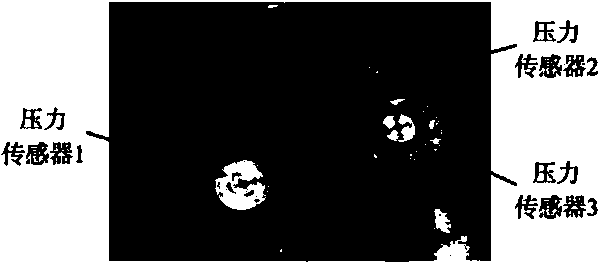
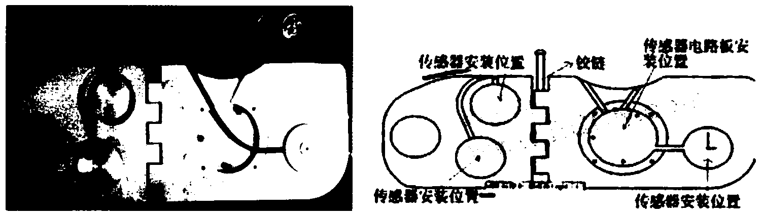
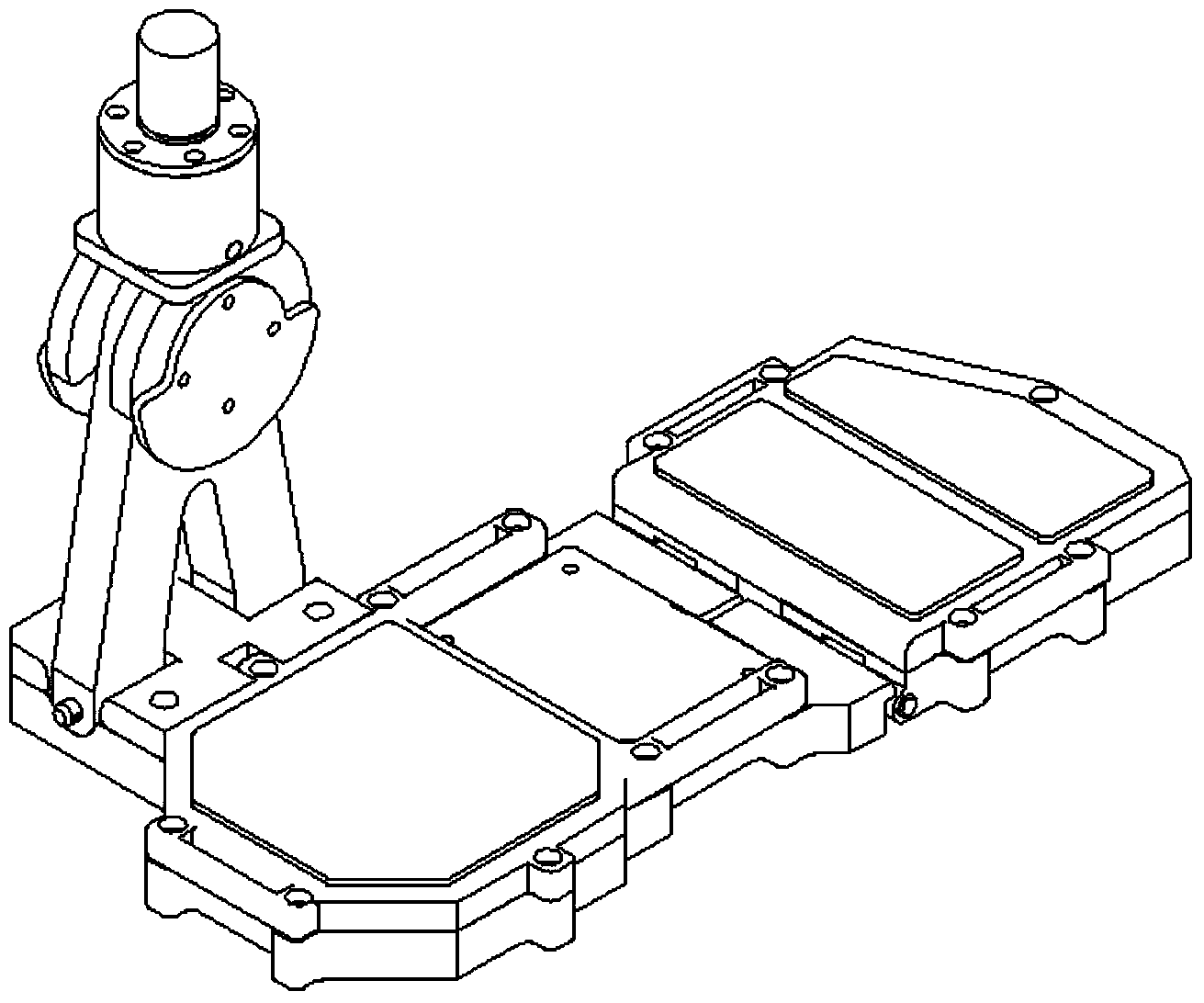
[0034] Such as image 3 As shown, the technical principle of the present invention is as follows: according to the physiological structure of the human foot, it is divided into several parts, and the parts are connected by mechanical joints; the degree of freedom of the joints is similar to that of the human foot joints, and can fit the human body when worn and used. Sports; according to the distribution of force on the soles of the human body, pressure sensors are arranged and equipped with force transmission structures; the sensors convert pressure signals into electrical signals and transmit them to the signal processing system through cables; the signal processing system obtains gait information through calculation, ...


PUM


Abstract

The invention belongs to the technical field of machines, and provides a foot applied force measuring device for a lower limb assistance system, wherein the foot applied force measuring device is convenient to wear, does not impede normal walking and running of a user, and protects the joints of the users against injuries. According to the foot physiological structure of a human body, the freedom degree of the joints is similar to that of the joints of the feet of the human body, and the foot applied force measuring device can be in fit with movements of the human body. According to the foot applied force distribution, pressure sensors are distributed, and force transmission structures are arranged. The sensors convert pressure signals into electric signals, the electric signals are transmitted to a signal processing system through a cable, and gait information is obtained through calculation, and sent to the outer world through a bus. Therefore, the foot applied force measuring device has the better man-machine suitability, meets the requirement of the lower limb assistance system and a similar system for foot applied force measuring analysis and load bearing, integrates gait analysis functions, does not influence the gait movements of the user, protects the user against injuries of deformation movements, and is accurate in force measurement, reliable in bearing, and wide in application prospect in similar assistance systems.

Description

technical field [0001] The invention belongs to the technical field of machinery, and in particular relates to a plantar force measuring device used in a lower limb assisting system. Background technique [0002] In equipment such as exoskeleton and rehabilitation training equipment for the disabled, it is necessary to monitor the force on the sole of the user. The existing plantar measurement system lacks the optimal design of sensor devices and mechanical structures, poor wearing comfort, loss of force measurement, and lack of protection; the sensing device itself does not have signal analysis and processing capabilities and communication functions. [0003] Such as figure 1 and figure 2 As shown, the characteristics of the existing two plantar force measuring devices are that the pressure sensor is directly exposed, and the user directly steps on it, which causes the contact area between the sensor and the user's sole to be too small, resulting in poor comfort for the ...

Claims


Application Information

Patent Timeline
IPC IPC(8): A61B5/22A61H3/00
Inventor 金昊龙宋慧新陈宇王超马明贾川侯友山肖洁赵宁曹宇
Owner CHINA NORTH VEHICLE RES INST
Why Eureka
Try Eureka