Switch capable of being triggered in multiple forms

A multi-form, switching technology, applied in the direction of contact meshing, contact drive mechanism, etc., can solve problems such as lack of versatility, and achieve the effect of reliable and durable structural characteristics

Inactive Publication Date: 2014-04-30
叶春林
View PDF6 Cites 0 Cited by
  • Summary
  • Abstract
  • Description
  • Claims
  • Application Information

AI Technical Summary

Problems solved by technology

[0003] The purpose of the present invention is to overcome the lack of versatility in the prior art, and to provide a multi-form contactable switch with a simple and reasonable structure, reliability and durability.

Method used


Image

  • Switch capable of being triggered in multiple forms
  • Switch capable of being triggered in multiple forms
  • Switch capable of being triggered in multiple forms

Examples


Embodiment 1

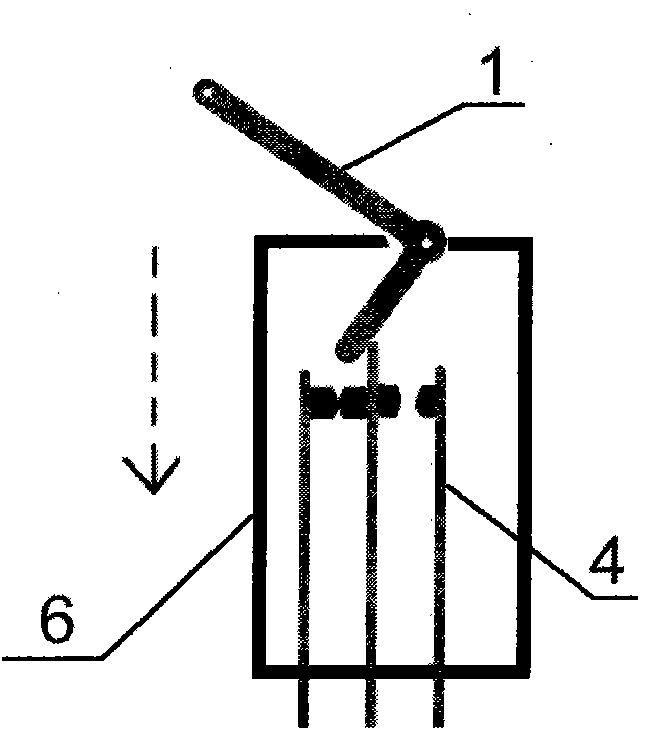
[0032] Embodiment 1: as figure 1 As shown, a switch capable of multi-form contact, which includes an angle-shaped intersection contact part 1 , a conductor part 4 and a housing part 6 . The angular intersection contact member 1 is a right-angled device formed by injection molding of nylon 1010. The end of the straight rod of the entire exposed housing member 6 is R-shaped, and is provided with a through hole for connecting a pull wire. The intersection point of right angle is used as rotating shaft support and is arranged on the frame line of housing part 6, and the cross bar end that places in housing part 6 is also R-shaped. The conductor piece 4 is a three-piece structure that is stamped and formed with C5191 phosphor bronze sheet, and has an outer lead wire that is press-formed. The middle piece is in contact with the conductor piece 4 on one side in a normally closed state. The setting is separated from the conductor part 4 on the other side and is normally open. The ho...

Embodiment 2

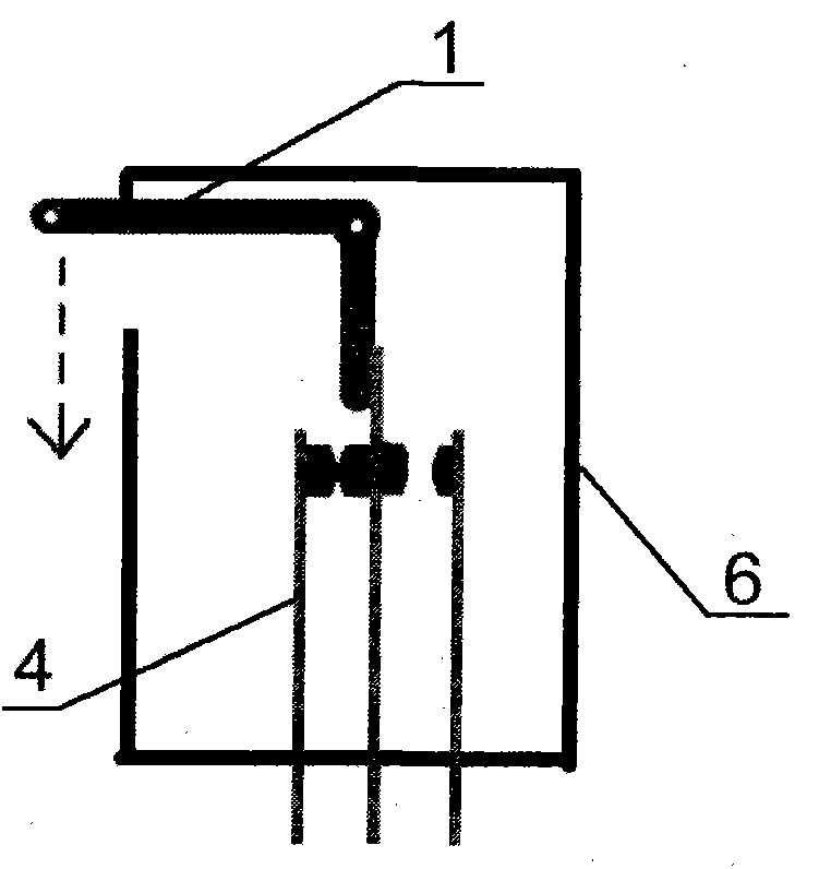
[0033] Embodiment 2: as figure 2As shown, it includes an angular junction contact piece 1 , a conductor piece 4 and a housing piece 6 . The angular intersection contact member 1 is a right-angled device formed by injection molding of nylon 1010, and the end of the straight rod exposed from the housing part 6 is R-shaped, and is provided with a through hole for connecting a pull wire. The intersection point is used as a rotating shaft to support and is arranged in the housing part 6, and the end of the cross bar placed in the housing part 6 is also R-shaped. The conductor piece 4 is a three-piece structure that is stamped and formed with C5191 phosphor bronze sheet, and has an outer lead wire that is press-formed. The middle piece is in contact with the conductor piece 4 on one side in a normally closed state. The setting is separated from the conductor part 4 on the other side and is normally open. The housing part 6 is a mating housing device formed by injection molding wi...

Embodiment 3

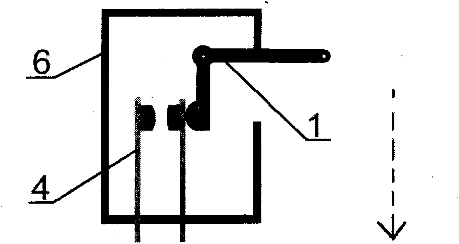
[0034] Implementation 3: If image 3 As shown, it includes an angular junction contact piece 1 , a conductor piece 4 and a housing piece 6 . The angular intersection contact member 1 is a right-angled device formed by injection molding of nylon 1010, and the end of the straight rod exposed from the housing part 6 is R-shaped, and is provided with a through hole for connecting a pull wire. The intersection point is used as a rotating shaft to support and be arranged in the housing part 6, and the end of the crossbar placed in the housing part 6 is also in the shape of a band R. The conductor part 4 is a two-piece structural part that is stamped and formed from a C5191 phosphor bronze sheet, and has an outer lead wire that is press-formed. The two parts are separated and normally open. The housing part 6 is a mating housing device formed by injection molding with the angular intersection branch contact communication part 1. The material is still nylon 1010, and the card for the...


PUM


Abstract

The invention discloses a switch capable of being triggered in multiple forms. The switch capable of being triggered in multiple forms comprises a conductor part, a triggering part and a shell part, wherein the conductor part arranged on the shell part is triggered in a contact mode by the triggering part through lever type force exerting triggering of a rotary shaft supporting structure, and the triggering part can achieve wire drawing type action, side moving type action and pressing and combining type action. The switch capable of being triggered in multiple forms has the advantages of being reasonable, simple, reliable and durable, capable of being triggered in multiple forms conveniently and flexibly, effectively suitable for various occasions, high in universality and capable of being widely used.

Description

technical field [0001] The invention relates to the field of tactile switches, in particular to a multi-form tactile switch which can be applied to acquire action signals of various mechanism devices. Background technique [0002] At present, there are many known ways to obtain the action signals of various mechanisms and devices, but they are generally not universal; especially to obtain the action signals of devices from the mechanisms that are already in use, and their spatial locations are limited. When there are requirements for reliability, stability and durability in use, qualified products will not be so easy to find, and it will easily become a troublesome problem. Contents of the invention [0003] The purpose of the present invention is to overcome the lack of versatility in the prior art, and to provide a multi-form contact switch with a simple and reasonable structure, reliability and durability. [0004] In order to achieve the above object, the present inve...

Claims


Application Information

Patent Timeline
Patent Type & Authority Applications(China)
IPC IPC(8): H01H1/12H01H3/32
Inventor 叶春林
Owner 叶春林
Why Eureka
Try Eureka