Diaphragm of flat panel speaker and earphone speaker with same

A flat-panel loudspeaker and flat-panel technology, applied in the field of loudspeakers, can solve the problems of difficult sound characteristics, uneconomical, R&D costs and long R&D cycle, etc., and achieve good sound effects, high-frequency response and transient balance effects

Active Publication Date: 2021-07-27
HEAD DIRECT KUNSHAN CO LTD
View PDF5 Cites 0 Cited by
  • Summary
  • Abstract
  • Description
  • Claims
  • Application Information

AI Technical Summary

Problems solved by technology

[0005] First of all, the use of gold as the material of the diaphragm coil mainly uses its good ductility to achieve a very thin thickness, so it is very uneconomical to improve the quality by increasing the thickness of the gold coil
[0006] Secondly, in the research and development process of the earphones, the final tuning style always depends on the actual listening of the human ear, which means that to master the ideal thickness or ideal thickness range of the gold coil, it is necessary to produce a large number of diaphragms with different coil thicknesses. This not only puts forward very high requirements on the manufacturing process of gold coils, but also the research and development costs and research and development cycle are too long, which is difficult for enterprises to afford.
Therefore, it is also very difficult to control the sound characteristics by controlling the thickness of the coil

Method used


Image

  • Diaphragm of flat panel speaker and earphone speaker with same
  • Diaphragm of flat panel speaker and earphone speaker with same
  • Diaphragm of flat panel speaker and earphone speaker with same

Examples


Embodiment 1

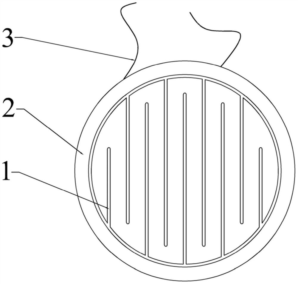
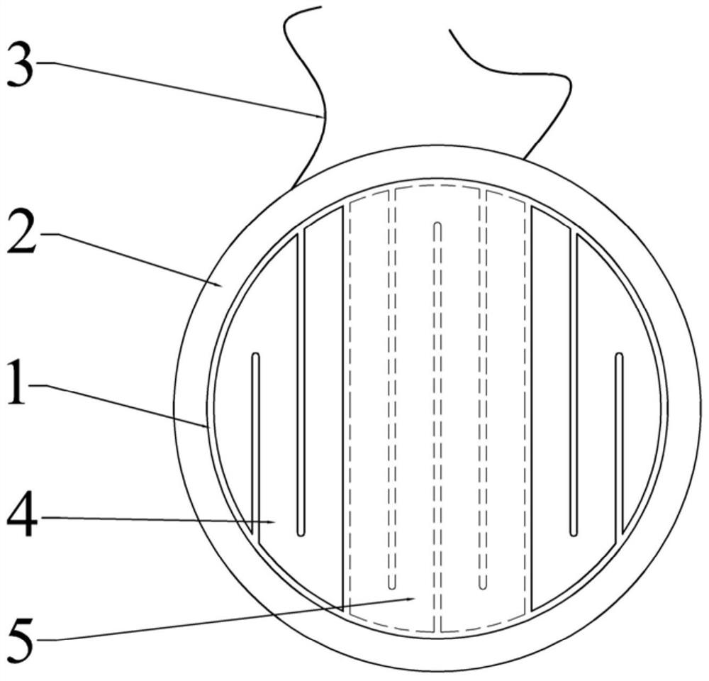
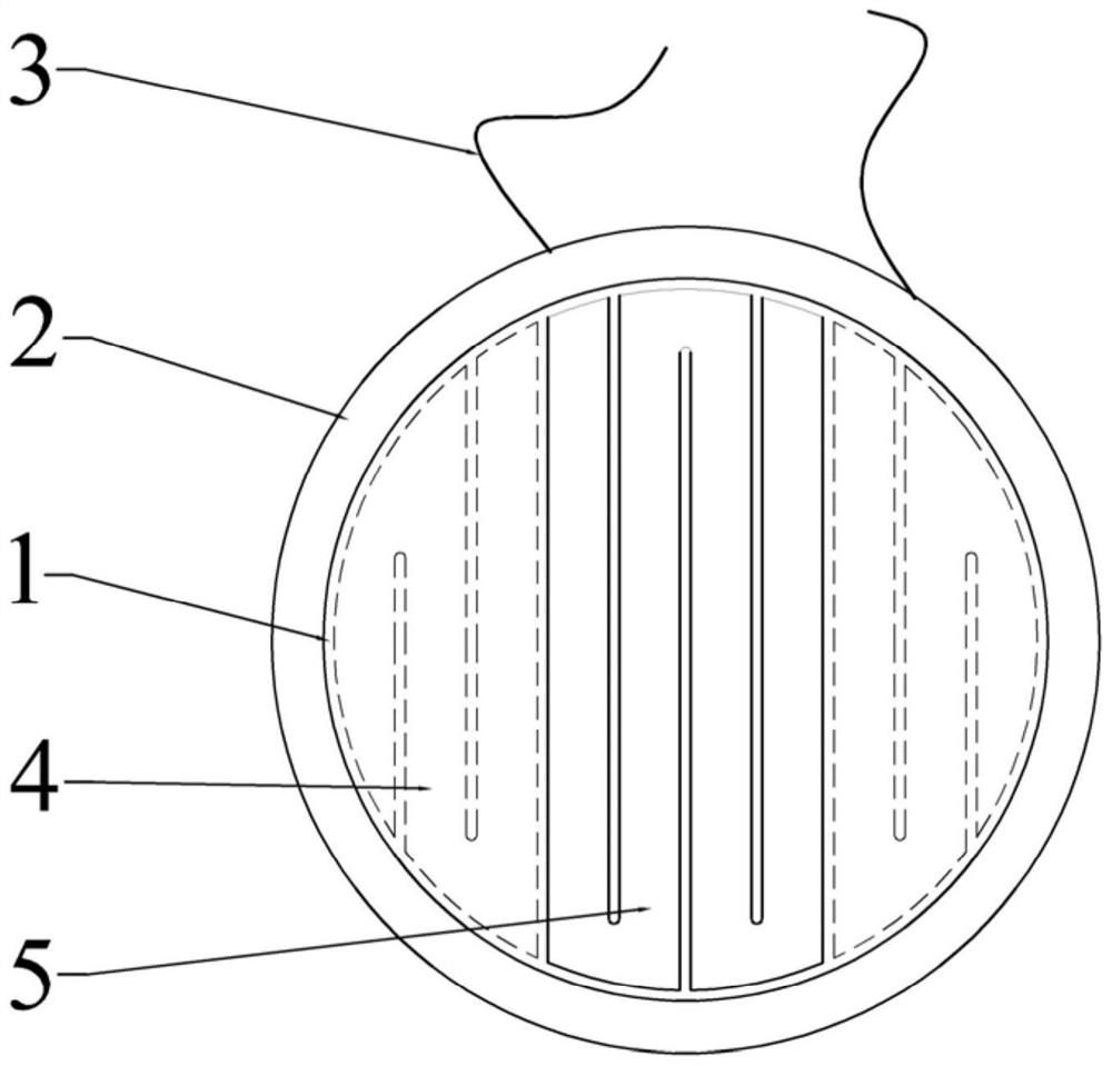
[0028] see Figure 2-3 As shown, the present embodiment 1 first proposes a flat panel speaker diaphragm, the diaphragm 1 is circular in shape, and its periphery is fixed on the frame 2, a voice coil is laid on the diaphragm 1, and a voice coil is also arranged on the frame 2 There are two wires 3 electrically connected to both ends of the voice coil. But what is different from the existing flat earphone diaphragm is that the voice coil is composed of two first sub-coils 4 and one second sub-coil 5 connected in series. The first sub-coil 4 is arranged on the first surface of the diaphragm 1, and the second sub-coil 5 is arranged on the second surface opposite to the first surface. in:

[0029] The second sub-coil 5 is formed by regular wiring of the second conductor material, and is arranged at the center of the diaphragm 1. The second sub-coil 5 has a meandering and serpentine structure. In this embodiment, the second conductor material is gold, and the second sub-coil 5 i...

Embodiment 2

[0039] This embodiment provides another diaphragm structure, and the difference from Embodiment 1 is that the first sub-coil 4 and the second sub-coil 5 on the diaphragm 1 are both arranged on the same side of the diaphragm 1 . Compared with the structure in embodiment 2, since the two coils in embodiment 1 are located on both sides of the diaphragm, the requirements for processing technology are relatively low, which is the preferred technical solution.


PUM


Abstract

The invention relates to a flat loudspeaker vibrating film and an earphone speaker with the vibrating film. The periphery of the diaphragm is fixed on the frame, the diaphragm is provided with a voice coil, the voice coil includes a first sub-coil and a second sub-coil connected in series, the second sub-coil is formed by a regular wiring of gold and platinum, and The projections of the first sub-coil and the second sub-coil on the plane where the diaphragm is located do not overlap; on the plane where the diaphragm is located, the quality of the first sub-coil with the same projected area is 2-2 of the second sub-coil. 30 times. Its advantages are: a flat-panel speaker diaphragm coil with a composite structure is formed by connecting multiple coils in series. One coil is made of gold or platinum with better ductility, and the other coil is made of other conventional metal materials. The length and area of ​​the coil are used to control the overall quality of the coil, and then control the sound characteristics of the speaker, so that the low and high frequency responses and transients are more balanced, and a good sound effect is achieved.

Description

technical field [0001] The invention relates to the technical field of loudspeakers, in particular to a flat-panel speaker diaphragm and an earphone speaker with the diaphragm. Background technique [0002] Flat-panel earphones combine the advantages of both dynamic earphones and electrostatic earphones. Compared with electrostatic earphones, they have better performance in low frequency and are stronger than dynamic earphones in high frequency. The structure of the core transducer is usually a plurality of strip permanent magnets arranged side by side on the yoke, and a diaphragm is arranged parallel to the magnetic pole faces of these permanent magnets, and the position on the diaphragm opposite to the permanent magnet Coils are provided. The current flowing inside the coil is perpendicular to the magnetic field generated by the permanent magnet, so that by passing an alternating current in the coil, the coil generates a force that obeys Faraday's law. Under the action of...

Claims


Application Information

Patent Timeline
Patent Type & Authority Patents(China)
IPC IPC(8): H04R7/02H04R9/06
Inventor 边仿
Owner HEAD DIRECT KUNSHAN CO LTD
Why Eureka
Try Eureka