Head-mounted flat-panel earphone

A head-mounted, flat-panel technology, applied in earphone/headphone accessories, etc., can solve the problems of difficult sound characteristics, uneconomical, R&D cost and long R&D cycle, and achieve good sound effect, high frequency response and transient balance. Effect

Active Publication Date: 2019-04-16
HEAD DIRECT KUNSHAN CO LTD
View PDF6 Cites 0 Cited by
  • Summary
  • Abstract
  • Description
  • Claims
  • Application Information

AI Technical Summary

Problems solved by technology

[0005] First of all, the use of gold as the material of the diaphragm coil mainly uses its good ductility to achieve a very thin thickness, so it is very uneconomical to improve the quality by increasing the thickness of the gold coil
[0006] Secondly, in the research and development process of the earphones, the final tuning style always depends on the actual listening of the human ear, which means that to master the ideal thickness or ideal thickness range of the gold coil, it is necessary to produce a large number of diaphragms with different coil thicknesses. This not only puts forward very high requirements on the manufacturing process of gold coils, but also the research and development costs and research and development cycle are too long, which is difficult for enterprises to afford.
Therefore, it is also very difficult to control the sound characteristics by controlling the thickness of the coil

Method used


Image

  • Head-mounted flat-panel earphone
  • Head-mounted flat-panel earphone
  • Head-mounted flat-panel earphone

Examples


Embodiment 1

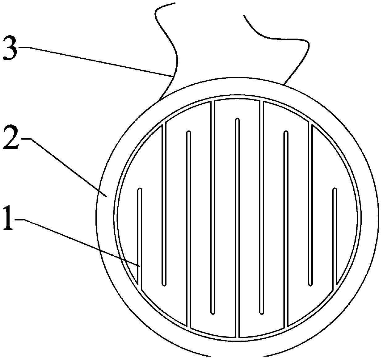
[0030] see Figure 2-3 As shown, the present embodiment 1 first proposes a planar earphone, which has a headband 6, a left earmuff 7 and a right earmuff 8 arranged at both ends of the headband 6, and a planar transducer placed in the left and right earmuffs. The structure of the planar transducer is the same as that of the conventional planar transducer, including a diaphragm 1 fixed on the frame 2 and a permanent magnet opposite to the coil on the diaphragm 1 . The permanent magnets can be arranged on both sides of the diaphragm 1 (push-pull type) or only on one side (unipolar type). Since this structure is familiar to those skilled in the art and does not belong to the design point of the present invention, it will not be repeated here.

[0031] The shape of the diaphragm 1 is circular, and its periphery is fixed on the frame 2 , a voice coil is laid on the diaphragm 1 , and two wires 3 electrically connected to both ends of the voice coil are arranged on the frame 2 . But...

Embodiment 2

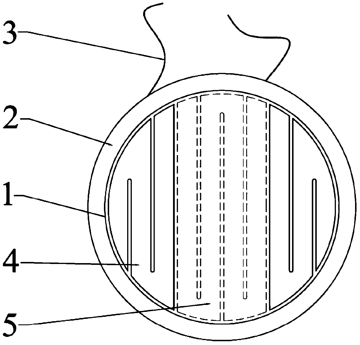
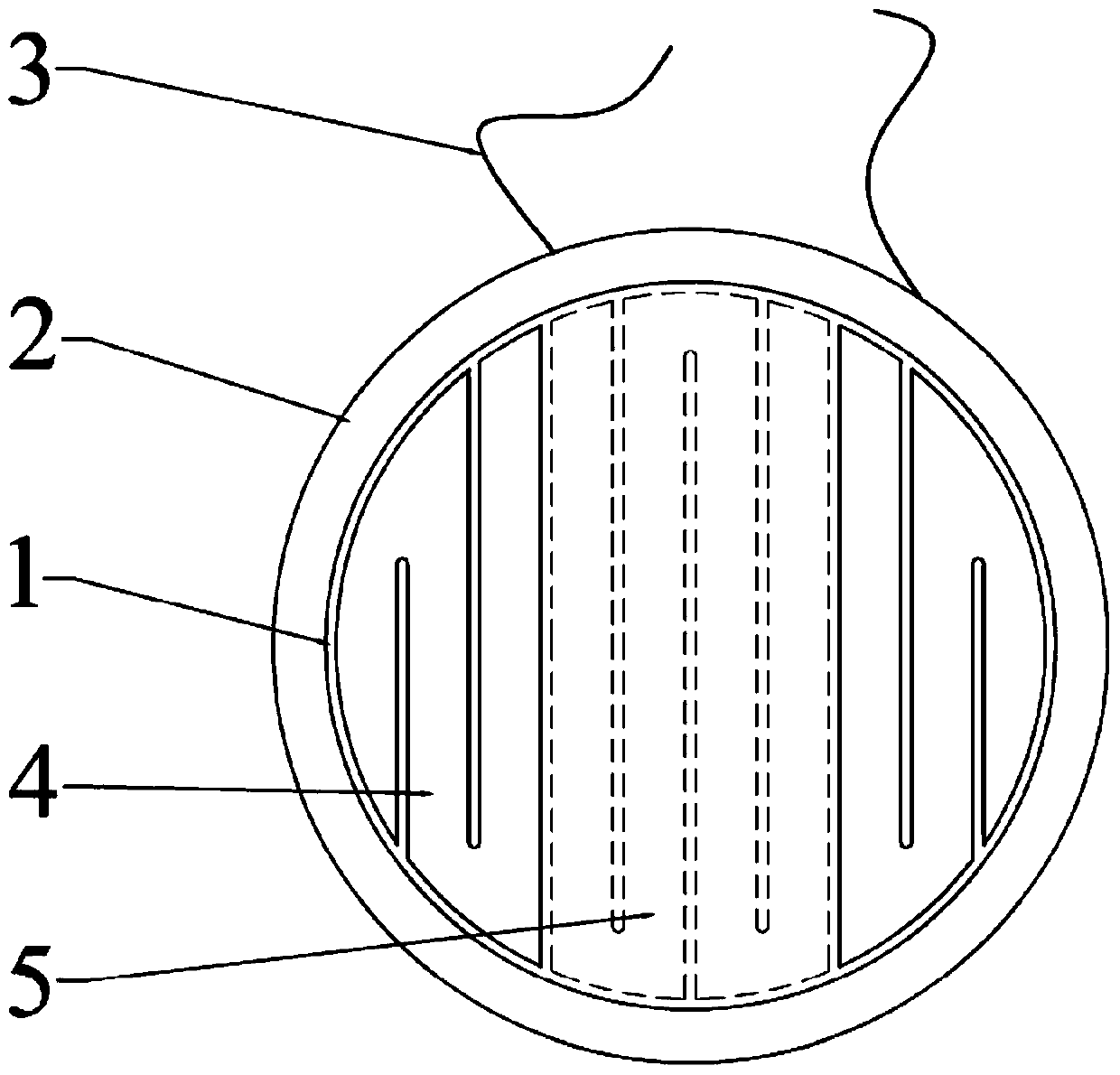
[0041] This embodiment provides another diaphragm structure, which differs from Embodiment 1 in that the first sub-coil 4 and the second sub-coil 5 on the diaphragm 1 are both arranged on the same side of the diaphragm 1 . Compared with the structure in embodiment 2, since the two coils in embodiment 1 are respectively located on both sides of the diaphragm, the requirements for processing technology are relatively low, which is the preferred technical solution.


PUM


Abstract

The invention relates to a head-mounted flat plate headset which comprises a headband, a left ear muff, a right ear muff, flat plate type transducers and a headset line, wherein the left ear muff and the right ear muff are arranged at the two ends of the headband, the flat plate type transducers are arranged in the ear muffs, the headset line provides signals for the flat plate type transducers, each flat plate type transducer comprises a vibrating diaphragm and a permanent magnet, the periphery of each vibrating diaphragm is fixed to a corresponding frame, and each permanent magnet is arranged corresponding to coils on the corresponding vibrating diaphragm. The headset is characterized in that each coil comprise a first sub-coil and a second sub-coil, the first sub-coils are in series connection with the second sub-coils, each first sub-coil is formed by a first conductor in a regular wiring mode, each second sub-coil is formed by a second conductor in a regular wiring mode, and projections of the first sub-coils on the vibrating diaphragms do not overlap with projections of the second sub-coils on the vibrating diaphragms. The headset has the advantages that the coils of the vibrating diaphragms of the flat plate type transducers of composite structures are formed in a multi-coil series connection mode, one kind of coils is made of gold or platinum good in malleability, the other kind of coils is made of other conventional metal materials, overall quality of the coils is controlled by control over lengths and areas of the two kinds of the coils, voice characteristics of the transducers are controlled, low-frequency response, high-frequency response and the transient state are well balanced, and a good voice effect is achieved.

Description

technical field [0001] The invention relates to the technical field of earphones, in particular to a head-mounted flat panel earphone. Background technique [0002] Flat-panel earphones combine the advantages of both dynamic earphones and electrostatic earphones. Compared with electrostatic earphones, they have better performance in low frequency and are stronger than dynamic earphones in high frequency. The structure of the core transducer is usually a plurality of strip permanent magnets arranged side by side on the yoke, and a diaphragm is arranged parallel to the magnetic pole faces of these permanent magnets, and the position on the diaphragm opposite to the permanent magnet Coils are provided. The current flowing inside the coil is perpendicular to the magnetic field generated by the permanent magnet, so that by passing an alternating current in the coil, the coil generates a force that obeys Faraday's law. Under the action of this force, the diaphragm vibrates in the...

Claims


Application Information

Patent Timeline
Patent Type & Authority Patents(China)
IPC IPC(8): H04R1/10
Inventor 边仿
Owner HEAD DIRECT KUNSHAN CO LTD
Why Eureka
Try Eureka