Active power line pole

A technology of power lines and poles, which is applied in the field of electric power equipment, can solve the problems of inconvenient height adjustment, need for manual operation, firmness of poles, poor stability, etc., and achieve the effects of improving convenience, reducing rainwater, and reducing the risk of leakage

Inactive Publication Date: 2016-01-13
DEZHOU POWER SUPPLY COMPANY OF STATE GRID SHANDONG ELECTRIC POWER +1
View PDF7 Cites 0 Cited by
  • Summary
  • Abstract
  • Description
  • Claims
  • Application Information

AI Technical Summary

Problems solved by technology

[0002] In the field of power facilities, the power line erecting pole is a kind of basic equipment for erecting power lines, and the current main power line erecting poles are fixed; however, for electric power construction or temporary construction sites, the required power line erecting pole It is best to be flexible and changeable. Although some current detachable racks can also adjust the position and height, and are easy to move; however, there are still the following problems: 1. The height adjustment is very inconvenient, and the rods are generally used to lengthen 1. It is not only troublesome to adjust the height of the base, but also the firmness and stability of the whole pole are poor; The bottom is a smooth cylinder. In rainy weather, the power pole will be exposed to rain from the top to the bottom. After that, the rainwater on the upper surface of the pole body will fall from top to bottom along the pole body, which will cause a lot of rainwater to adhere to the lower surface of the pole body. The human body often leans against the lower surface of the pole body. In this case, if the insulation above the pole is slightly poor, it is easy to cause an electric shock to the human body near the pole body; 3. For the power line pole required for power testing, It is usually hoped to know the current situation passing through the pole. In this case, the transformer is generally used for measurement, which requires manual operation, which is troublesome, and a relatively long path of induction wires needs to be laid, and the induction wires still need to be well prepared. Leakage Protection Measures

Method used


Image

  • Active power line pole
  • Active power line pole

Examples


Embodiment Construction

[0009] The present invention will be further described below in conjunction with the drawings and embodiments:

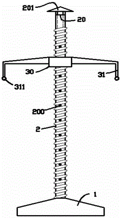
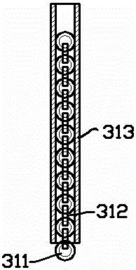
[0010] figure 1 Shown here is a schematic diagram of an embodiment of a movable power line rack pole, where the movable power line rack pole includes a base 1, a rod body 2 fixed above the base, and a bracket matched with the rod body 2; the rod body 2 is Screw, the bracket includes a bolt rotating body 30 that matches with the screw, and wiring legs 31 symmetrically fixed on both sides of the bolt rotating body 30. The lower end of the wiring legs 31 is provided with a threading ring 311, The power line passes through and rests inside; the rod body 2 is tubular, and the inside is a hollow passage through up and down, and the upper end 20 of the rod body is provided with a rain cap 201, and the rain cap 201 and the upper end 20 of the rod body have a transverse air Flow gap; the rod body 2 is provided with radial holes 200 communicating with the hollow channel at equal...


PUM


Abstract

The invention provides a movable power line bracket rod which comprises a base, a rod body which is fixed above the base, and a bracket which is matched with the rod body, wherein the rod body is a screw rod; the bracket comprises a bolt rotating body which is matched with the screw rod, and wiring supporting feet which are symmetrically fixed on both sides of the bolt rotating body; the rod body is tubular, the inner part of the rod body is a hollow passage of which the top and the bottom are communicated, a rain cap is arranged at the upper end of the rod body, and a gap for supplying the air to horizontally flow is formed between the rain cap and the upper end of the rod body; radial holes are equidistantly formed in the rod body in the axial direction of the rod body from top to bottom, and the radial holes are communicated with the hollow passage and formed in the screw groove bottom of the rod body. The altitude of the movable power line bracket rod can be conveniently adjusted, and the electric leakage risk of the lower surface can be reduced greatly.

Description

Technical field [0001] The present invention relates to the field of power equipment, in particular, to a power line pole. Background technique [0002] In the field of power facilities, power line poles are basic equipment used to erect power lines. The current main power line poles are fixed; however, for power construction or temporary construction sites, the required power line poles It is best to be flexible and changeable. Although some of the current removable rack rods can also be adjusted in position and height, and are easy to move; however, there are still the following problems: 1. The height adjustment is very inconvenient, and the rods are generally extended , The way of heightening the base for adjustment is not only troublesome, but also the firmness and stability of the whole frame is poor; 2. Because there are many opportunities for construction personnel to approach the temporary frame, the surface of the ordinary temporary frame is from top to The bottom is a...

Claims


Application Information

Patent Timeline
Patent Type & Authority Patents(China)
IPC IPC(8): E04H12/18E04H12/24
CPCE04H12/182
Inventor 周波曹平郭立泉李亦农李冰李晓博张帅
Owner DEZHOU POWER SUPPLY COMPANY OF STATE GRID SHANDONG ELECTRIC POWER
Why Eureka
Try Eureka