
A detection method for maliciously shielding GPS antenna

A technology of GPS antenna and detection method, applied in the field of GPS positioning, can solve the problems of unable to locate normally, reduce GPS satellite signals, GPS terminal paralysis, etc., achieve the effect of real-time monitoring of vehicle operation and prevent malicious damage by others

Active Publication Date: 2018-05-22
XIAMEN YAXON NETWORKS CO LTD
View PDF4 Cites 0 Cited by
  • Summary
  • Abstract
  • Description
  • Claims
  • Application Information

AI Technical Summary

Problems solved by technology

Because the GPS antenna can be said to be the eyes of the entire GPS terminal, once the antenna is damaged, the GPS will not be able to locate, then the so-called monitoring, tracking, positioning, and other auxiliary functions will all fail, and the entire GPS terminal will basically be paralyzed
[0003] For destroying the GPS antenna, there are currently three common methods. One is to directly unplug or cut the GPS antenna (that is, cause the GPS antenna to open), so that it cannot be positioned normally; the other is to short the positive and negative poles of the GPS antenna together. (That is to cause a short circuit of the GPS antenna), so that it cannot be positioned normally; the other is to use a metal shield to cover the GPS antenna, reducing the GPS satellite signal so that it cannot be positioned normally
Among them, the first two methods already have related technologies to achieve effective detection, but the third method has not yet been detected by reliable technology, which creates an opportunity for malicious saboteurs

Method used


Image

  • A detection method for maliciously shielding GPS antenna
  • A detection method for maliciously shielding GPS antenna

Examples


Embodiment Construction

[0022] The present invention will be further described in conjunction with specific embodiments.

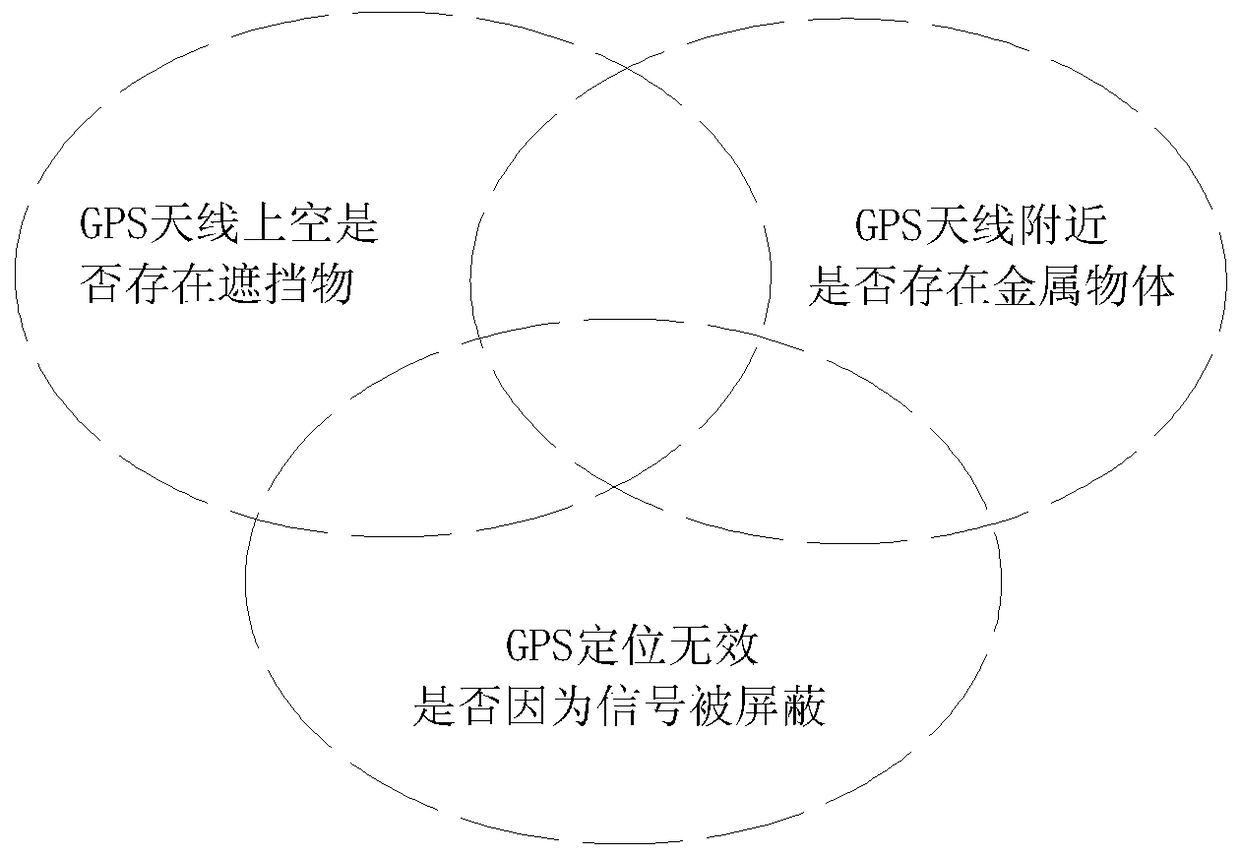
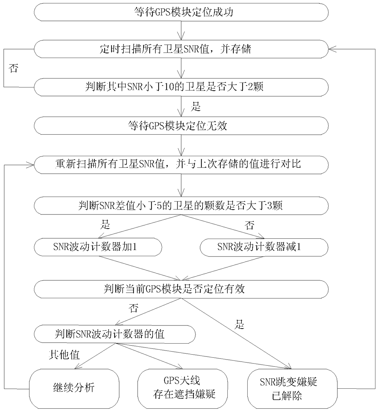
[0023] The technical solution of the invention is to comprehensively and effectively detect whether the GPS antenna is shielded maliciously by adopting a combination of hardware circuit and software algorithm. First, a set of invisible light transmitters and receivers is used to detect whether there is an opaque shield over the GPS antenna; at the same time, a metal proximity sensor is used to detect whether there are additional metal objects near the GPS antenna; A set of SNR value comparison algorithm is used to confirm whether the GPS non-location is caused by malicious interference or shielding of GPS satellite signals.

[0024] In order to improve the detection effect and ensure no misjudgment, this mechanism adopts a combination of two hardware circuit detection and one set of software algorithm judgment. The three rely on each other and restrain each other to achieve a tru...


PUM


Abstract

The invention discloses a detection method for GPS antenna malicious shielding. The detection method comprises the steps that firstly, whether GPS positioning is effective or not is detected, if GPS positioning is invalid, the suspicion that a GPS antenna is shielded and cannot be positioned exists, and whether the GPS positioning invalid phenomenon is caused by signal shielding or not is judged through the SNR algorithm; if the calculation result is true, it is determined that the GPS antenna is shielded maliciously, and then the second step is executed to conduct malicious shielding detection; secondly, an invisible light emitter and an invisible light receiver are arranged inside an GPS antenna receiving head, the invisible light emitter is responsible for emitting outwards signals of invisible light with the designated wavelength, the invisible light receiver is responsible for receiving the signals of the invisible light, whether shielding objects exist outside the GPS antenna or not is judged by detecting whether the receiver receives the signals of the invisible light with the designated wavelength or not, and if the receiver receives the signals of the invisible light with the designated wavelength sent by the emitter, it is indicated that the GPS antenna is shielded maliciously.

Description

technical field [0001] The invention belongs to the technical field of GPS positioning, and in particular relates to a detection mechanism for maliciously shielding a GPS antenna. Background technique [0002] At present, most of the vehicles are installed with vehicle-mounted GPS positioning terminals, not because of the needs of the vehicle owners themselves, but because the vehicle administrators (such as companies, dealers, etc.) need to monitor the operation and working conditions of the vehicles. Monitoring and, if necessary, remote control of the vehicle. For car owners, these purposes are contrary to their original intentions. Of course, they do not want the vehicle to be monitored in real time or even remotely controlled, so they will come up with various methods to secretly destroy the car GPS terminal, so that it cannot work normally. Work in order to achieve the purpose of getting rid of being monitored and controlled by others. Among them, the most common and ...

Claims


Application Information

Patent Timeline
Patent Type & Authority Patents(China)
IPC IPC(8): G01S19/23
CPCG01S19/23
Inventor 姚亮陈从华黄运峰蔡运文汤益明李家祥
Owner XIAMEN YAXON NETWORKS CO LTD
Learn More