Wireless remote meter reading fee-control electric energy meter

A wireless centralized reading and electric energy meter technology, which is applied in the direction of measuring electric variables, signal transmission systems, measuring devices, etc., can solve the problems of limited meter reading distance, additional wiring, and difficult implementation, and achieves convenient meter reading, simple networking, and fully functional effects

Inactive Publication Date: 2012-04-18
宁夏隆基宁光仪表股份有限公司
View PDF12 Cites 11 Cited by
  • Summary
  • Abstract
  • Description
  • Claims
  • Application Information

AI Technical Summary

Problems solved by technology

[0002] The electronic energy meter reading methods commonly used now mainly include meter reading methods such as 485 communication, infrared communication, and carrier communication. These meter reading methods greatly shorten the time-consuming manual meter reading, but are limited by meter reading equipment and Table environment, low work efficiency
[0003] Although the traditional meter reading mode has been widely recognized and vigorously promoted by the society, the work efficiency is low and difficult to achieve in special environments. For example, in the vast rural areas, electric energy meters are installed in meter boxes high It is almost impossible to install cumbersome communication lines for RS485 meter reading, and it is impossible to use infrared handheld computers; in urban communities, additional wiring is required if RS485 meter reading is used, and the meter reading distance is limited , it is not easy to be widely used; if the carrier wave method is used for meter reading, the real-time performance of meter reading is not good, and the success rate of meter reading cannot meet the requirements, which cannot meet the needs of electricity consumption statistics

Method used


Image

  • Wireless remote meter reading fee-control electric energy meter
  • Wireless remote meter reading fee-control electric energy meter
  • Wireless remote meter reading fee-control electric energy meter

Examples


Embodiment Construction

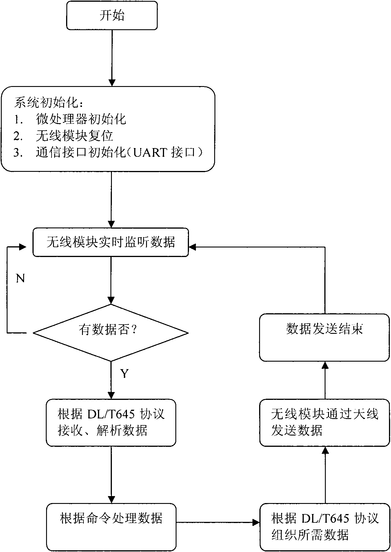
[0014] The present invention will be described in further detail below in conjunction with accompanying drawing:

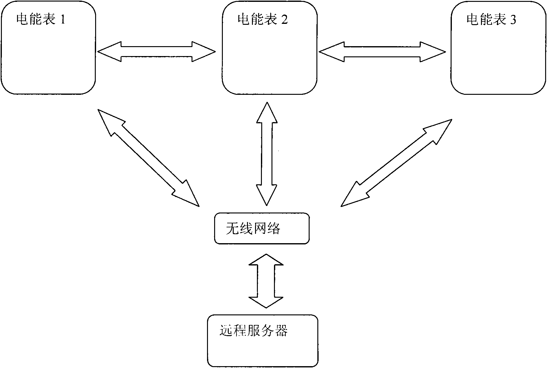
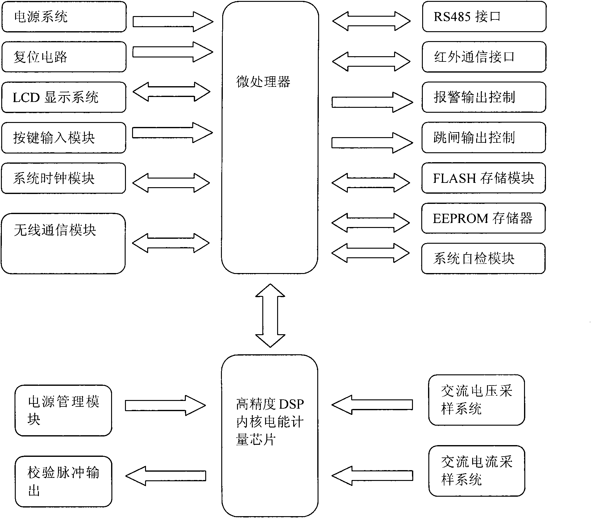
[0015] The invention discloses a fully sealed design three-phase wireless micro-power centralized reading remote transmission cost control electric energy meter, the electric energy meter mainly includes a special high-precision electric energy metering chip, a high-speed 32-bit high-performance embedded microprocessor based on the ARM7 core , special system clock, power management module, infrared communication interface, RS485 communication interface, wireless module communication interface, GPRS module, LCD display, large-capacity data storage system, tripping and closing relay and other parts of the circuit, the communication module on the energy meter is online The status LED indicator indicates the connection status between the energy meter and the communication network, and there are also remote data receiving and sending LED indicators to indicate the energ...


PUM


Abstract

The invention relates to an electronic-type fee-control electric energy meter and particularly relates to a wireless remote meter reading fee-control electric energy meter. The electric energy meter comprises a microprocessor and is characterized by also comprising a wireless communication module with the microprocessor, thus realizing two-way communication with a remote server through a wireless network. Compared with the prior art, the electric energy meter provided by the invention has the following advantages: 1, meter reading is convenient, so that a power supply department does not need to carry out fussy meter reading in a user power utilization field but only needs to carrying out wireless remote meter reading; and 2, the user power utilization condition and the power grid operating condition can be monitored in real time, and task monitoring and real-time stationary measurement are customized through a master station, so that the power utilization condition and the power grid operating parameter can be analyzed.

Description

technical field [0001] The invention relates to an electronic fee-controlled electric energy meter, in particular to a wireless centralized copy remote transmission fee-controlled electric energy meter. Background technique [0002] The electronic energy meter reading methods commonly used now mainly include meter reading methods such as 485 communication, infrared communication, and carrier communication. These meter reading methods greatly shorten the time-consuming manual meter reading, but are limited by meter reading equipment and Table environment, low work efficiency. [0003] Although the traditional meter reading mode has been widely recognized and vigorously promoted by the society, the work efficiency is low and difficult to achieve in special environments. For example, in the vast rural areas, electric energy meters are installed in meter boxes high It is almost impossible to install cumbersome communication lines for RS485 meter reading, and it is impossible to...

Claims


Application Information

Patent Timeline
Patent Type & Authority Applications(China)
IPC IPC(8): G01R11/02G08C17/02
Inventor 常兴智马恩赐罗长荣
Owner 宁夏隆基宁光仪表股份有限公司
Why Eureka
Try Eureka