
Spindle bearing device, textile machine, method for operating spindle bearing device, and use of O-shaped ring element

A bearing device and textile machine technology, applied in a field, can solve the problems of changing suspension and damping properties, complex spindle bearing device, etc., and achieve the effects of improving axial damping capacity, saving installation space, and improving axial damping capacity.

Active Publication Date: 2014-05-14
SAURER COMPONENTS GMBH
View PDF6 Cites 1 Cited by
  • Summary
  • Abstract
  • Description
  • Claims
  • Application Information

AI Technical Summary

Problems solved by technology

Although this spindle bearing arrangement appears to allow variable mounting of different spindles, the spindle bearing arrangement has suspension and damping properties that vary greatly relative to each other, for varying operating temperatures
Furthermore, such a spindle bearing arrangement is relatively complex, in particular due to the separate components compared to the radially acting damping arrangement

Method used


Image

  • Spindle bearing device, textile machine, method for operating spindle bearing device, and use of O-shaped ring element
  • Spindle bearing device, textile machine, method for operating spindle bearing device, and use of O-shaped ring element
  • Spindle bearing device, textile machine, method for operating spindle bearing device, and use of O-shaped ring element

Examples


Embodiment Construction

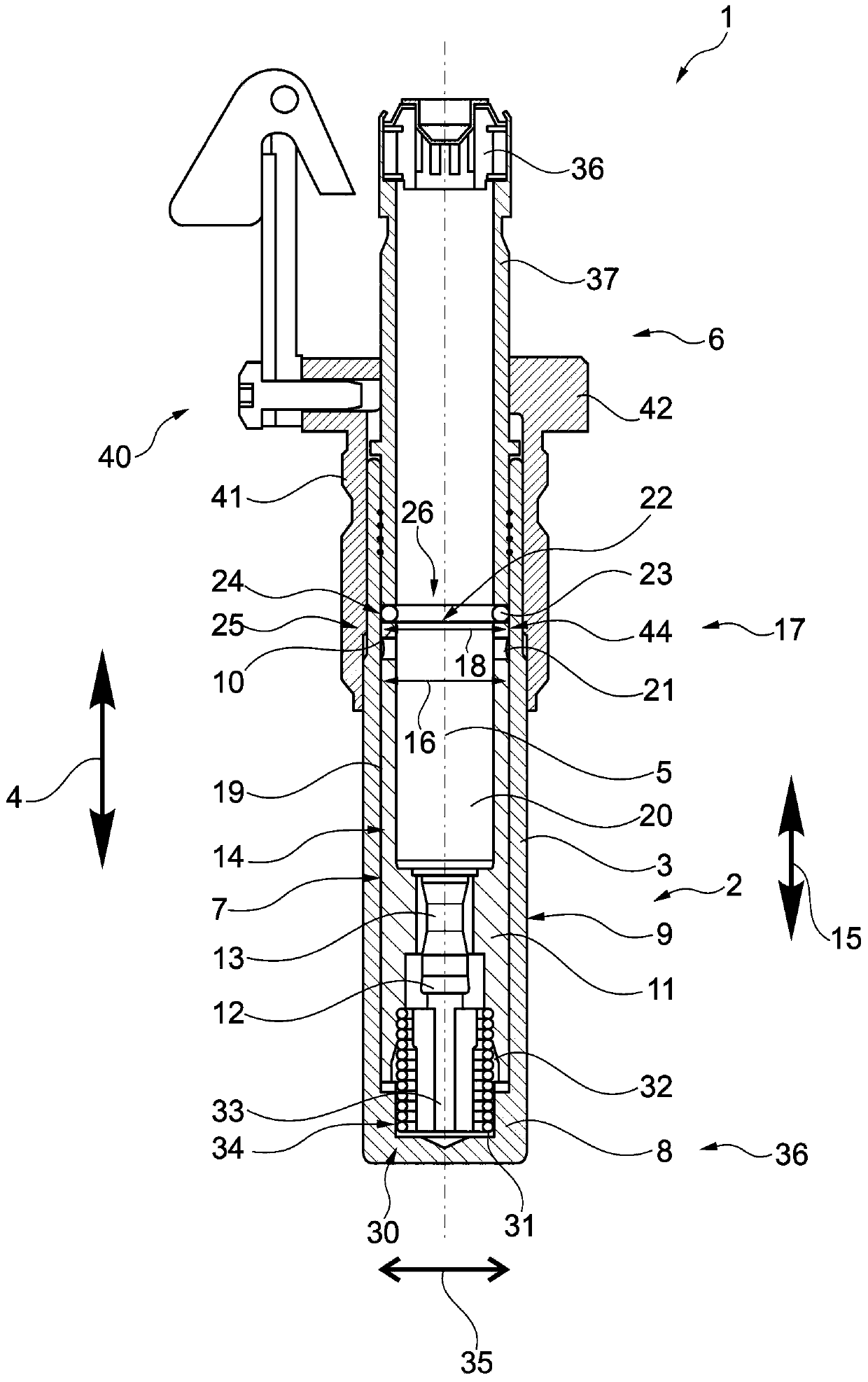
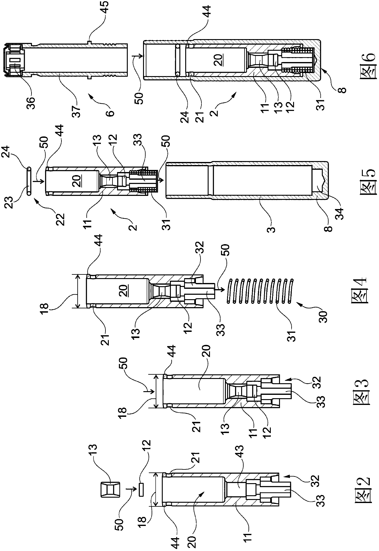
[0107] Figure 1 to Figure 6 The illustrated first spindle bearing arrangement 1 according to the invention for mounting a spinning spindle (not shown here) is equipped with a spindle step unit 2 which is mounted according to the invention in an axially prestressed manner on In the housing sleeve 3 of the spindle bearing device 1 .

[0108] Although the axially prestressed spindle step unit 2 can be displaced within the housing sleeve 3 due to this axial prestressing in the axial direction 4 with respect to the central axis 5, the spindle tube unit 6 in the other Aspects are arranged to be at least partially pressed into the housing sleeve 3 .

[0109] The bearing space 7 for the spindle step unit 2 is thus limited by the base area 8 of the housing sleeve 3 , the side wall area 9 of the housing sleeve 3 and the underside 10 of the spindle tube unit 6 pressed into the housing sleeve 3 . Thus, the spindle step unit 2 is fixed in such a way that it cannot be lost in the housin...


PUM


Abstract

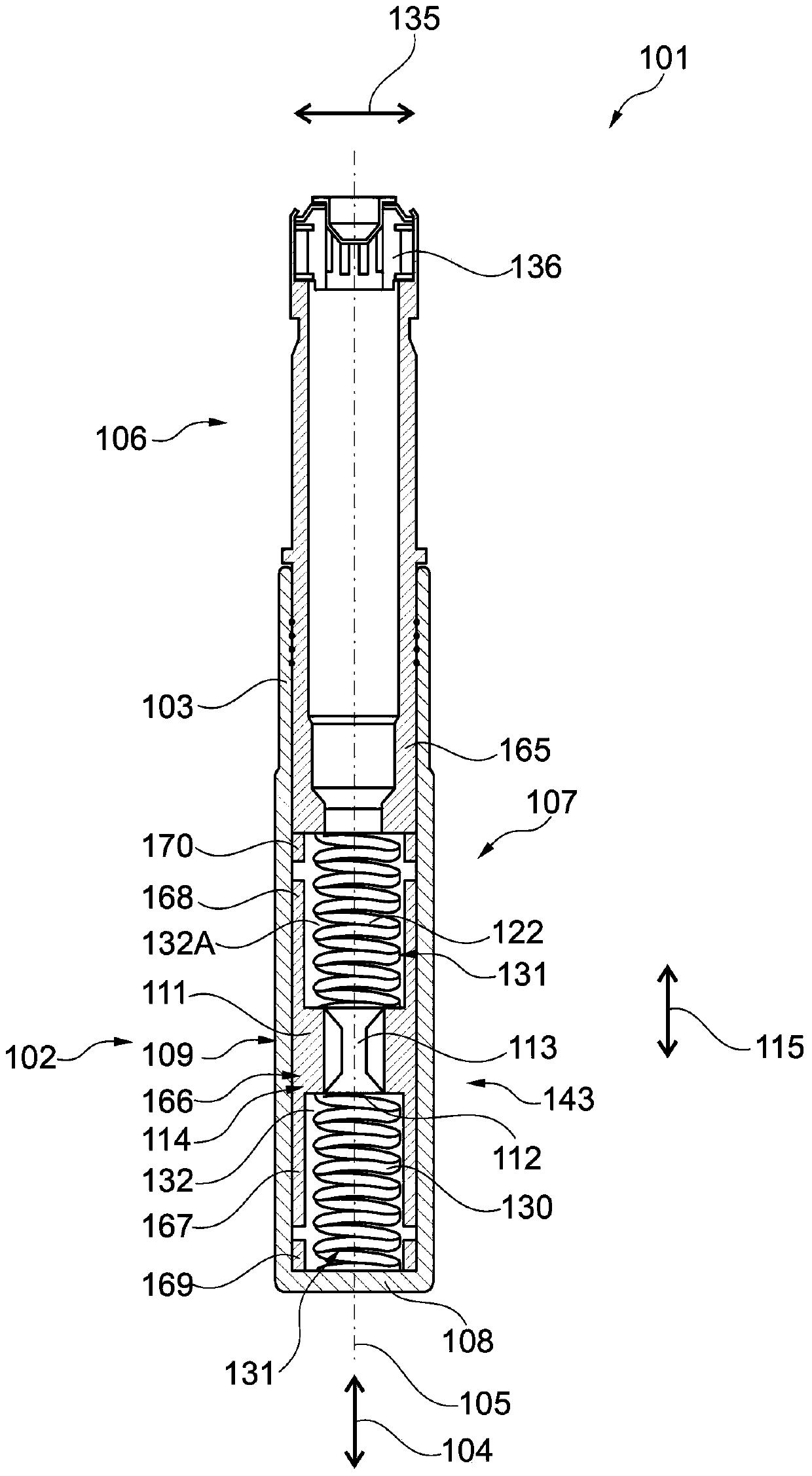
The present invention relates to a spindle bearing device for mounting a spindle. The spindle bearing device comprises a casing sleeve for supporting a spindle collar unit and a spindle foot support unit. The spindle foot support unit includes a bearing sleeve member for a spindle axial bearing element for axially mounting the spindle and a spindle radical bearing element for racially mounting the spindle to be arranged together in the bearing sleeve member. According to the invention, the bearing sleeve member of the spindle foot step unit is arranged inside the casing sleeve in an axial prestressing manner relative to the spindle collar unit; and the bearing sleeve member is loaded by a first spring element, in particular a helical compression spring element, and a second spring element, in particular an elastically deformable elastomer body element, wherein the first spring element is arranged between a base region of the casing sleeve and the bearing sleeve member, and the second spring element is arranged between the bearing sleeve member and the spindle collar unit.

Description

technical field [0001] One aspect of the invention relates to a spindle bearing arrangement for mounting a spindle having a housing sleeve for holding a spindle tube unit and a spindle step unit, wherein the spindle step unit comprises a bearing sleeve element, a spindle axial bearing for axially mounting the spindle The element is arranged in the bearing sleeve element together with the spindle radial bearing element for radially mounting the spindle. [0002] In another aspect, the invention relates to a textile machine having at least one spinning, twisting or rewinding spindle. [0003] Furthermore, the invention relates to a method for operating a spindle bearing arrangement comprising a spindle tube unit and a spindle step unit for mounting the spindle on a textile machine, wherein the spindle is on the one hand supported by means of the spindle axial bearing element of the spindle step unit And by means of the spindle radial bearing element of the spindle step unit, it...

Claims


Application Information

Patent Timeline
IPC IPC(8): D01H7/12
CPCD01H7/045D01H7/10D01H7/12
Inventor U·奥斯瓦德戈特弗里德·施陶登迈尔约瑟夫·温特
Owner SAURER COMPONENTS GMBH
Learn More