The guardrail for the expansion connection between the surface tube and the column

A technology for expanding and tightening connections and columns, which is applied in the connection of rods, connecting components, mechanical equipment, etc., can solve the problems of shortened service life of guardrails and guard windows, no adjustable space, and influence on mechanical strength, etc. The effect of improving the anti-push and pull ability and improving the installation efficiency

Active Publication Date: 2015-10-28
HUNAN GOLDWELL NEW MATERIALS TECH CO LTD
View PDF5 Cites 0 Cited by
  • Summary
  • Abstract
  • Description
  • Claims
  • Application Information

AI Technical Summary

Problems solved by technology

In the prior art, fasteners are generally used to pass through the outer wall of the surface tube and then directly threaded with the connector. At the same time, the connector is also connected to the column through the fastener. When this structure is used for connection, the surface tube and the column are evenly connected. It needs to be drilled and tapped. Too many holes on the surface tube will affect its mechanical strength. The connection between the surface tube and the column needs to be accurately positioned to achieve installation. There is no adjustable space, which greatly affects the installation efficiency. The force is mainly concentrated on the fasteners, and the stress points of the fasteners are prone to shear force and fracture failure, which also shortens the service life of guardrails and protective windows

Method used


Image

  • The guardrail for the expansion connection between the surface tube and the column
  • The guardrail for the expansion connection between the surface tube and the column
  • The guardrail for the expansion connection between the surface tube and the column

Examples


Embodiment 1

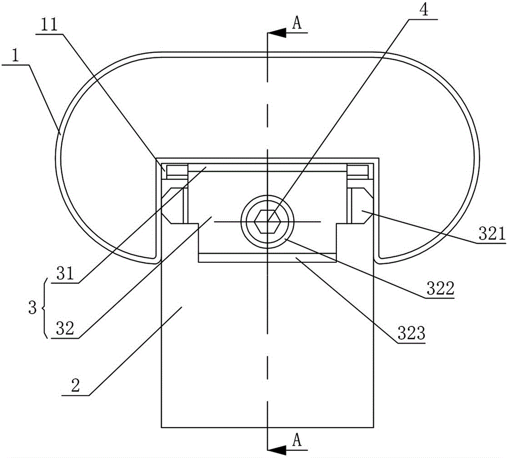
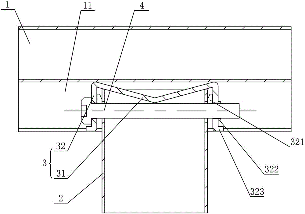
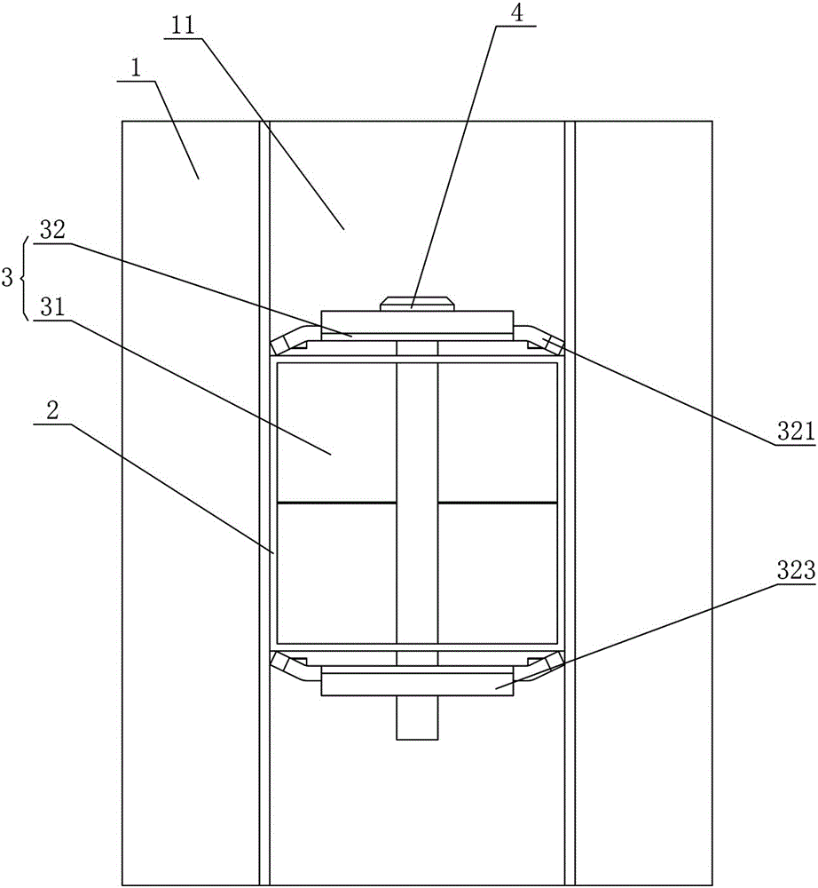
[0037] Figure 1 to Figure 5 It shows the first embodiment of the guardrail in which the surface pipe and the column are tightly connected in the present invention. The assembled guardrail includes the surface pipe 1, the column 2 and the expansion joint 3, and the expansion joint 3 is installed on the end of the column 2 through the screw rod 4 Head, the bottom of the surface tube 1 is provided with a groove 11 for the expansion joint 3, which has a simple structure and is easy to install. 3 is connected to the column 2, and then the groove 11 at the bottom of the surface tube 1 is placed on the outside of the expansion joint 3 to realize the pre-installation of the surface tube 1 and the column 2, and the screw 4 is further tightened to drive the expansion joint 3 to be clamped on the The outer wall of the end of the column 2 and the expansion joint 3 are expanded and connected with the groove 11, so as to realize the installation of the surface pipe 1 and the column 2. Comp...

Embodiment 2

[0042] Figure 6 to Figure 8It shows the second embodiment of the guardrail in which the surface pipe and the column are expanded and tightened according to the present invention. The assembled guardrail is basically the same as that of Embodiment 1, the only difference is that the expansion joint 3 includes a top plate 31 and two sides of the top plate 31. The side plates 32 and the top plate 31 are inclined to the inside of the expansion joint 3, and one of the side plates 32 is bent inwardly with a pressure edge 321 on both sides. At the same time, the two side plates 32 are clamped to the outer wall of the end of the column 2, and the pressure edge 321 on one of the side plates 32 expands and connects with the side wall of the groove (11), and the top plate 31 faces the expansion joint 3 Tilting can ensure that when the screw rod 4 is tightened, the top plate 31 is easily deformed, so that the clamping edge 321 and the other side plate 32 are clamped to the outer wall of t...

Embodiment 3

[0045] Figure 9 to Figure 11 It shows the third embodiment of the guardrail in which the surface pipe and the column are expanded and tightened according to the present invention. The assembled guardrail is basically the same as that of Embodiment 1, the only difference is that the expansion joint 3 includes a top plate 31 and two sides of the top plate 31. Side plates 32, wherein the two sides of one side plate 32 are bent with side edges 324, and the ends of the two sides 324 are bent with jacking edges 325 inclined inwardly, and the side plates 32 are provided with threaded holes that cooperate with the screw rod 4 322, when the screw rod 4 is tightened, the two side plates 32 are clamped to the outer wall of the end of the column 2, and the jacking edge 325 is driven by the thrust of the screw rod 4 to expand the side edge 324 to both sides to expand and connect with the side wall of the groove 11 Push the lifting edge 325 through the screw 4, so that the lifting edge 325...


PUM


Abstract

The invention discloses a guardrail achieving expansion connection between a surface tube and a stand column. The guardrail comprises the surface tube, the stand column and an expansion joint, wherein the expansion joint is arranged at the end of the stand column through a screw rod, a groove used for installation of the expansion joint in a sleeved mode is arranged in the bottom of the surface tube, and when the screw rod is screwed, the expansion joint is clamped to the outer wall of the end of the stand column and the expansion joint is expanded and is in expansion connection with the groove. The guardrail has the advantages that the structure is simple, stability is good and the surface tube can be installed later.

Description

technical field [0001] The invention mainly relates to pipe connection technology, in particular to a guardrail in which surface pipes and upright posts are expanded and tightly connected. Background technique [0002] In fields such as guardrails and protective windows, the connection between the surface pipe and the column needs to be realized through a connecting piece. In the prior art, fasteners are generally used to pass through the outer wall of the surface tube and then directly threaded with the connector. At the same time, the connector is also connected to the column through the fastener. When this structure is used for connection, the surface tube and the column are evenly connected. It needs to be drilled and tapped. Too many holes on the surface tube will affect its mechanical strength. The connection between the surface tube and the column needs to be accurately positioned to achieve installation. There is no adjustable space, which greatly affects the install...

Claims


Application Information

Patent Timeline
Patent Type & Authority Patents(China)
IPC IPC(8): F16B7/00F16B7/18
Inventor 谢斌泉
Owner HUNAN GOLDWELL NEW MATERIALS TECH CO LTD
Why Eureka
Try Eureka