Guardrail achieving expansion connection between surface tube and stand column
A technology for expanding and tightening connections and columns, which is applied in the connection of rods, connecting components, mechanical equipment, etc., can solve the problems of shortened service life of guardrails and guard windows, no adjustable space, and influence on mechanical strength, etc. The effect of improving the anti-push and pull ability and improving the installation efficiency
- Summary
- Abstract
- Description
- Claims
- Application Information
AI Technical Summary
Problems solved by technology
Method used
Image
Examples
Embodiment 1
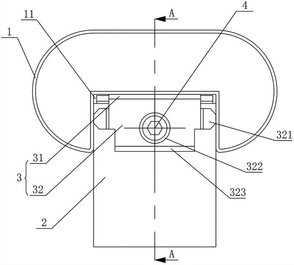
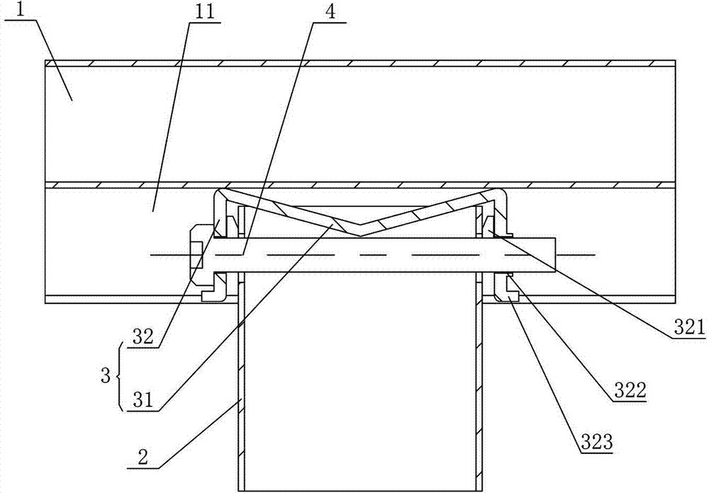
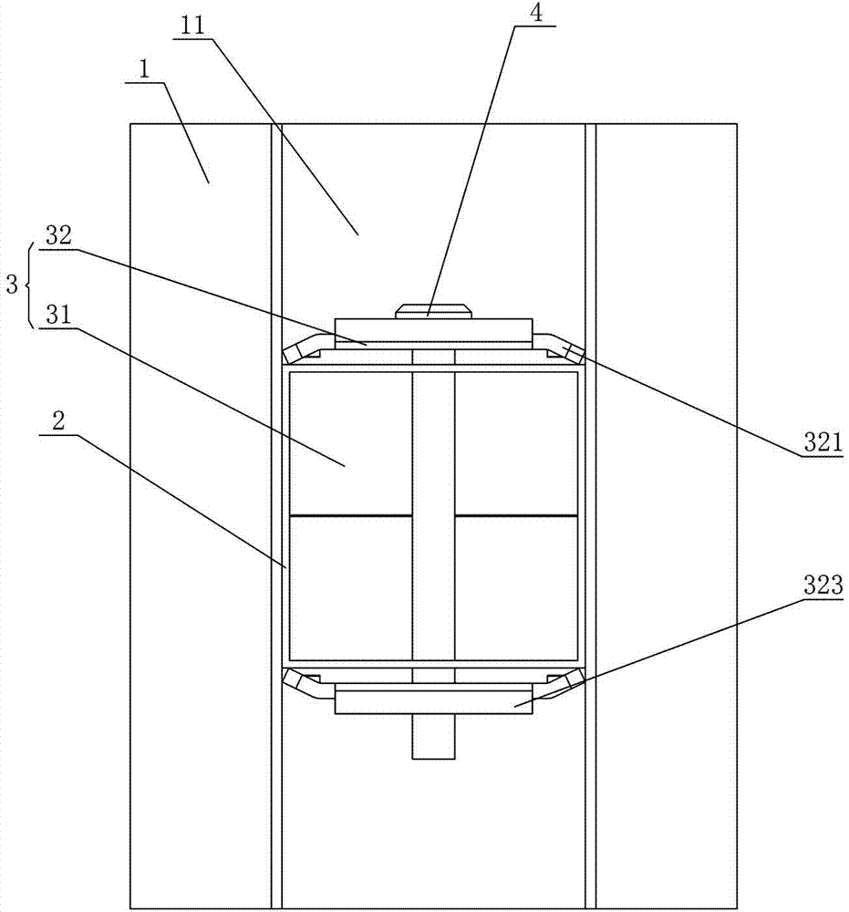
[0037] Figure 1 to Figure 5 It shows the first embodiment of the guardrail in which the surface pipe and the column are tightly connected in the present invention. The assembled guardrail includes the surface pipe 1, the column 2 and the expansion joint 3, and the expansion joint 3 is installed on the end of the column 2 through the screw rod 4 Head, the bottom of the surface tube 1 is provided with a groove 11 for the expansion joint 3, which has a simple structure and is easy to install. 3 is connected to the column 2, and then the groove 11 at the bottom of the surface tube 1 is placed on the outside of the expansion joint 3 to realize the pre-installation of the surface tube 1 and the column 2, and the screw 4 is further tightened to drive the expansion joint 3 to be clamped on the The outer wall of the end of the column 2 and the expansion joint 3 are expanded and connected with the groove 11, so as to realize the installation of the surface pipe 1 and the column 2. Comp...
Embodiment 2
[0042] Figure 6 to Figure 8It shows the second embodiment of the guardrail in which the surface pipe and the column are expanded and tightened according to the present invention. The assembled guardrail is basically the same as that of Embodiment 1, the only difference is that the expansion joint 3 includes a top plate 31 and two sides of the top plate 31. The side plates 32 and the top plate 31 are inclined to the inside of the expansion joint 3, and one of the side plates 32 is bent inwardly with a pressure edge 321 on both sides. At the same time, the two side plates 32 are clamped to the outer wall of the end of the column 2, and the pressure edge 321 on one of the side plates 32 expands and connects with the side wall of the groove (11), and the top plate 31 faces the expansion joint 3 Tilting can ensure that when the screw rod 4 is tightened, the top plate 31 is easily deformed, so that the clamping edge 321 and the other side plate 32 are clamped to the outer wall of t...
Embodiment 3
[0045] Figure 9 to Figure 11 It shows the third embodiment of the guardrail in which the surface pipe and the column are expanded and tightened according to the present invention. The assembled guardrail is basically the same as that of Embodiment 1, the only difference is that the expansion joint 3 includes a top plate 31 and two sides of the top plate 31. Side plates 32, wherein the two sides of one side plate 32 are bent with side edges 324, and the ends of the two sides 324 are bent with jacking edges 325 inclined inwardly, and the side plates 32 are provided with threaded holes that cooperate with the screw rod 4 322, when the screw rod 4 is tightened, the two side plates 32 are clamped to the outer wall of the end of the column 2, and the jacking edge 325 is driven by the thrust of the screw rod 4 to expand the side edge 324 to both sides to expand and connect with the side wall of the groove 11 Push the lifting edge 325 through the screw 4, so that the lifting edge 325...
PUM
 Abstract
Description
Claims
Application Information
 - R&D
- Intellectual Property
- Life Sciences
- Materials
- Tech Scout
- Unparalleled Data Quality
- Higher Quality Content
- 60% Fewer Hallucinations
Browse by: Latest US Patents, China's latest patents, Technical Efficacy Thesaurus, Application Domain, Technology Topic, Popular Technical Reports.
© 2025 PatSnap. All rights reserved.Legal|Privacy policy|Modern Slavery Act Transparency Statement|Sitemap|About US| Contact US: help@patsnap.com


