Faucet hydroelectric generator

a hydroelectric generator and hydroelectric technology, applied in the direction of electric generator control, renewable energy generation, greenhouse gas reduction, etc., can solve the problems of increased generated thrust force, increased wear, severe wear, etc., to reduce the deformation of the lid, increase the number of ribs, and increase the pressure receiving area

Active Publication Date: 2013-06-11
TOTO LTD
View PDF10 Cites 12 Cited by
  • Summary
  • Abstract
  • Description
  • Claims
  • Application Information

AI Technical Summary

Benefits of technology

[0020]As described above, if the lid is provided at the upstream end of the bucket blade, the lid can eliminate water flowing out to the upstream side from the bucket blade. This can increase water flowing in the bucket flow channel. Hence, the power generation efficiency can be increased.
[0066]Consequently, this can lead to improvement in attachment workability, improvement in bearing strength against forces from various directions, high power generation efficiency, and reduction of the thrust force.

Problems solved by technology

However, with the increase of flow rate, the generated thrust force increases, and hence the wear may increase.
In particular, in the faucet hydroelectric generator provided in a faucet device with a water discharge flow rate of approximately 8 liters / min or more, the wear may be severe.

Method used


Image

  • Faucet hydroelectric generator
  • Faucet hydroelectric generator
  • Faucet hydroelectric generator

Examples


Embodiment Construction

[0094]Embodiments of the invention will now be illustrated with reference to the drawings. In the drawings, similar components are labeled with like reference numerals, and the detailed description thereof is omitted as appropriate.

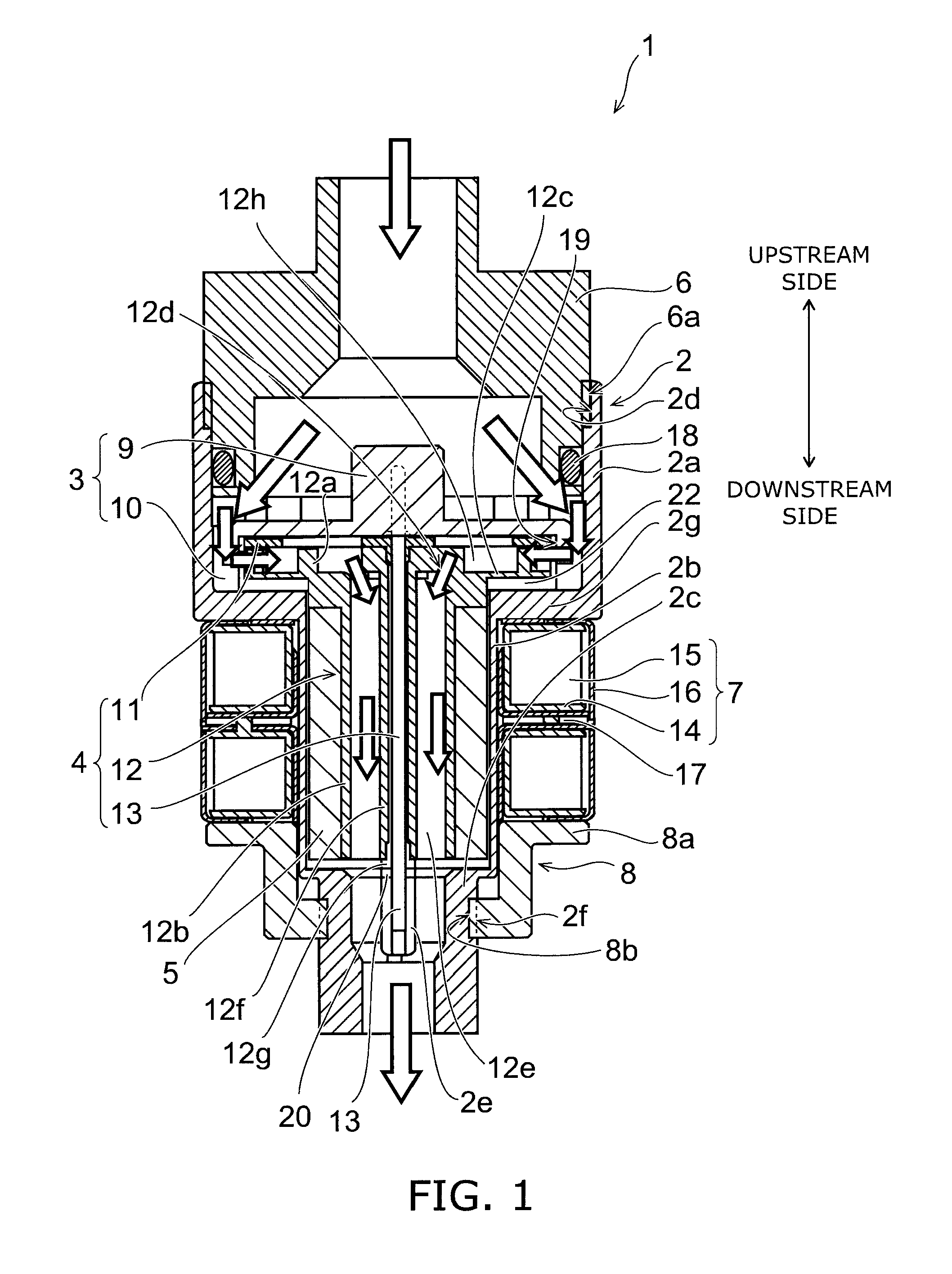
[0095]FIG. 1 is a schematic sectional view for illustrating a faucet hydroelectric generator according to an embodiment of the invention.

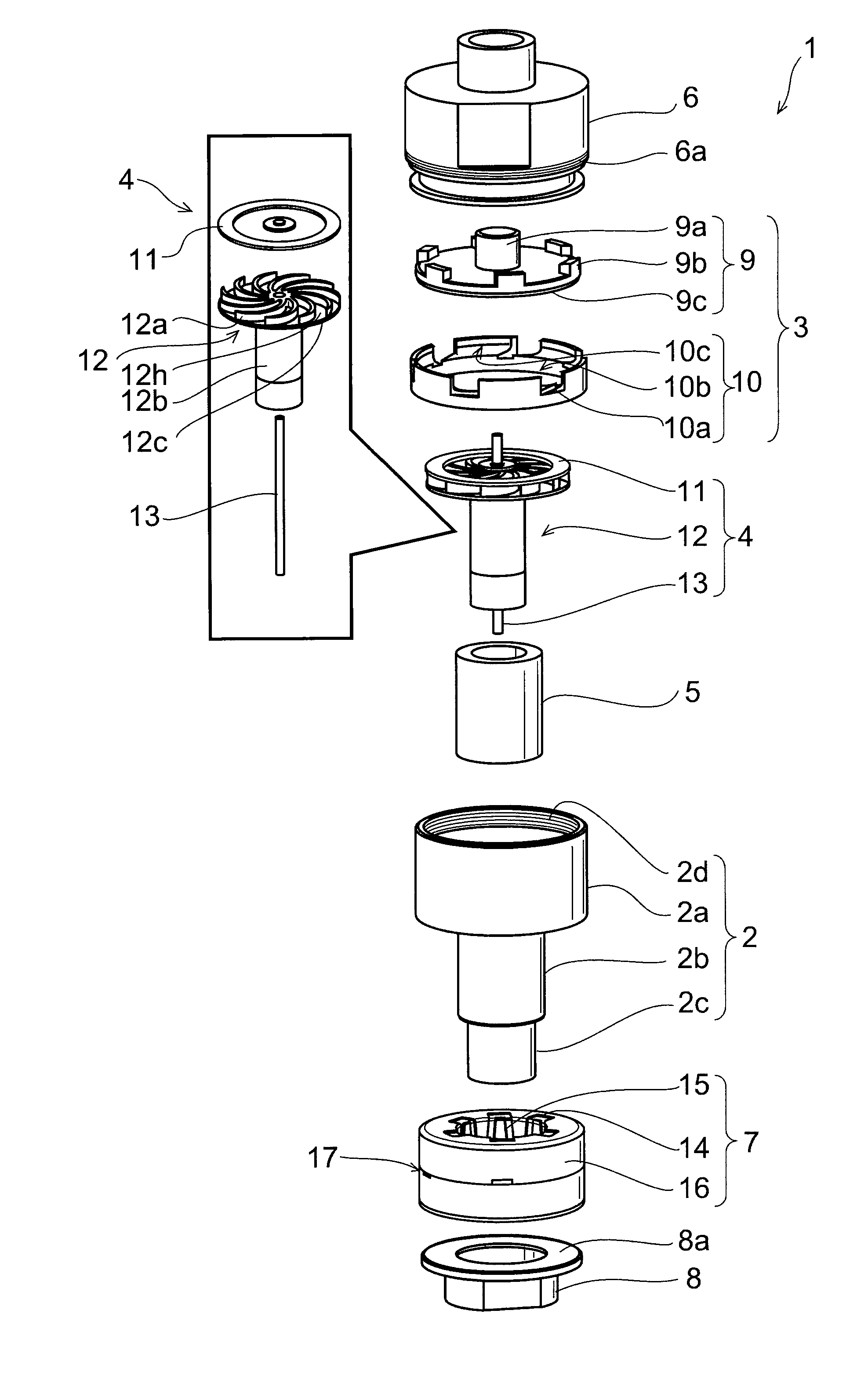
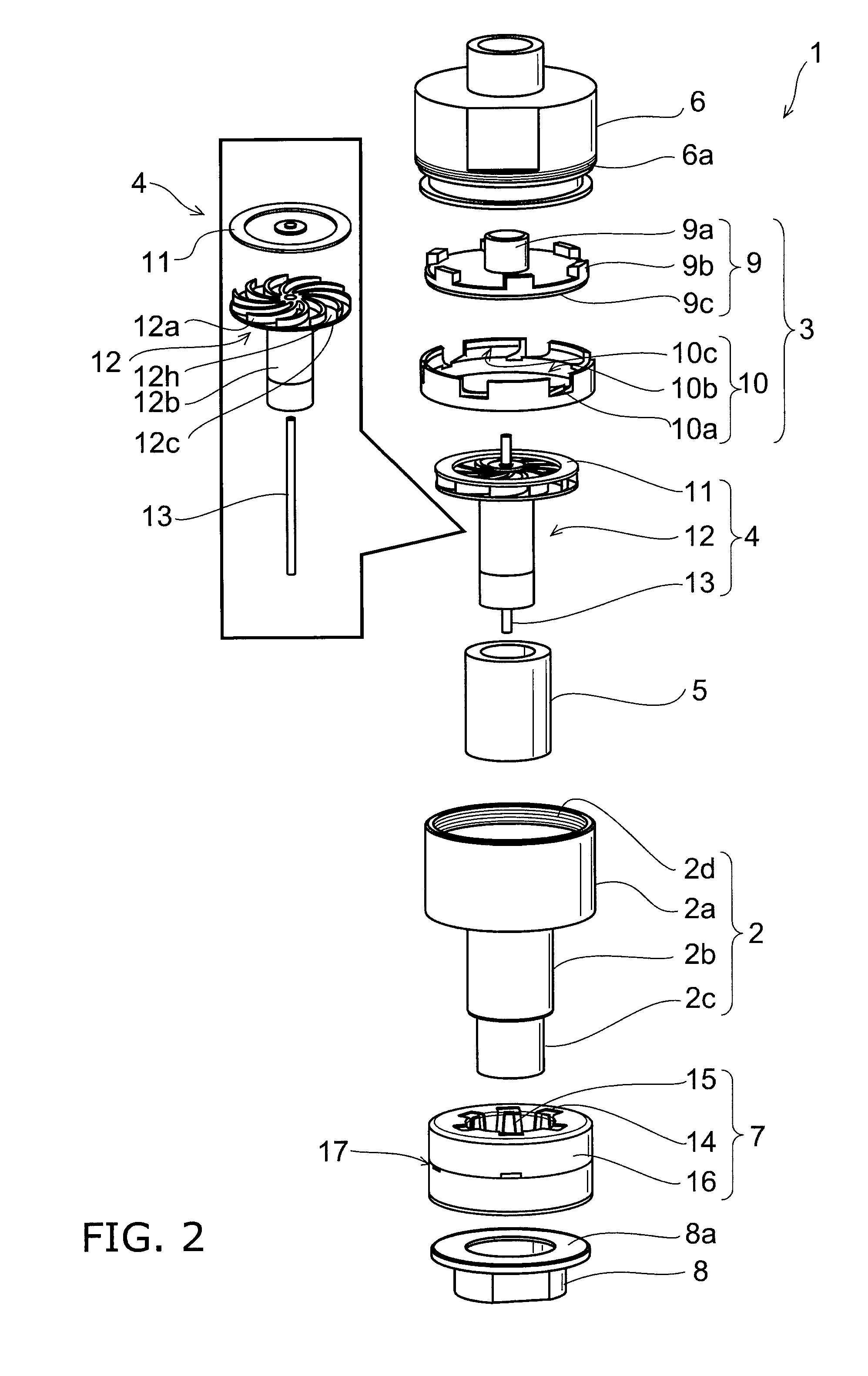
[0096]FIG. 2 is a schematic exploded view of the faucet hydroelectric generator according to the embodiment of the invention.

[0097]FIGS. 3A and 3B are schematic views for describing installation examples of the faucet hydroelectric generator according to the embodiment of the invention.

[0098]First, the installation examples of the faucet hydroelectric generator 1 shown in FIGS. 3A and 3B are described.

[0099]FIGS. 3A and 3B illustrate so-called shower faucet devices 100, 100a provided with the faucet hydroelectric generator 1.

[0100]Such shower faucet devices 100, 100a are provided in a bathroom, for instance. Here, FIG. 3...


PUM


Abstract

According to one embodiment, a faucet hydroelectric generator includes: a cylinder portion including a supply water inflow port and a supply water outflow port and having a supply water flow channel formed therein; a bucket having a rotation center axis generally parallel to the supply water flow channel, and including a bucket blade provided in the supply water flow channel so as to be rotatable about the rotation center axis; a magnet rotatable integrally with the bucket; a coil configured to generate electromotive force by rotation of the magnet; a nozzle portion including a plurality of injection ports configured to cause incoming water flowing parallel to the rotation center axis to be squirted in a plane generally perpendicular to the rotation center axis from radially outside the bucket blade toward the bucket blade; and a lid provided at an upstream end of the bucket blade and configured to rotate integrally with the bucket blade. The lid includes a thrust reducer configured to reduce a thrust force applied to the bucket.

Description

CROSS-REFERENCE TO RELATED APPLICATIONS[0001]This application is based upon and claims the benefit of priority from the prior Japanese Patent Application No. 2009-225578, filed on Sep. 29, 2009; the entire contents of which are incorporated herein by reference.BACKGROUND OF THE INVENTION[0002]1. Field of the Invention[0003]This invention generally relates to a faucet hydroelectric generator, and more particularly a faucet hydroelectric generator generating electric power using a flow of water supply.[0004]2. Description of the Related Art[0005]Recently, faucet devices have often been equipped with electrical systems. For instance, there is known a faucet device equipped with a sensor for sensing a hand stretched out below the tap, and a solenoid valve for opening / closing the water supply channel based on the signal from the sensor. As another example, an LED (light emitting diode) lamp is incorporated near the water discharge port to change the color of light shed on the discharged ...

Claims


Application Information

Patent Timeline
Patent Type & Authority Patents(United States)
IPC IPC(8): F03B13/00
CPCF03B3/00F03B13/00F05B2220/602F05B2220/604Y02B10/50Y02E10/223Y02E10/28Y02E10/20
Inventor KUROISHI, MASAHIROONODERA, NAOYUKISATO, TOMOKO
Owner TOTO LTD
Why Eureka
Try Eureka