fence

A guardrail and column technology, which is applied in the connection of poles, connecting components, mechanical equipment, etc., can solve the problems of shortened service life of guardrails and guard windows, no adjustable space, affecting installation efficiency, etc., and achieves simple structure, anti-push and pull. The effect of improving capacity and improving installation efficiency

Active Publication Date: 2016-03-30
HUNAN GOLDWELL NEW MATERIALS TECH CO LTD
View PDF5 Cites 0 Cited by
  • Summary
  • Abstract
  • Description
  • Claims
  • Application Information

AI Technical Summary

Problems solved by technology

In the prior art, fasteners are generally used to pass through the outer wall of the surface tube and then directly threaded with the connector. At the same time, the connector is also connected to the column through the fastener. When this structure is used for connection, the surface tube and the column are evenly connected. It needs to be drilled and tapped. Too many holes on the surface tube will affect its mechanical strength. The connection between the surface tube and the column needs to be accurately positioned to achieve installation. There is no adjustable space, which greatly affects the installation efficiency. The force is mainly concentrated on the fasteners, and the stress points of the fasteners are prone to shear force and fracture failure, which also shortens the service life of guardrails and protective windows

Method used


Image

  • fence
  • fence
  • fence

Examples


Embodiment 1

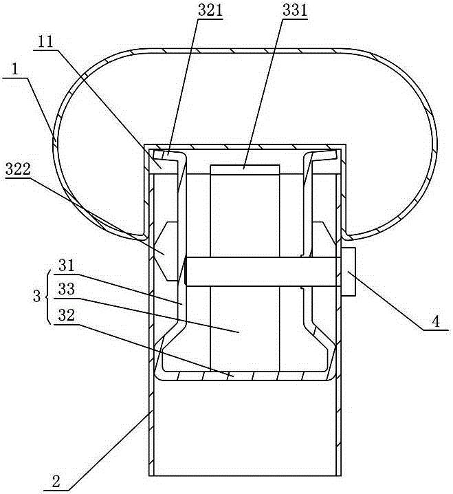
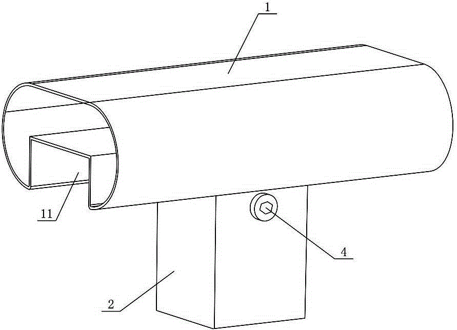
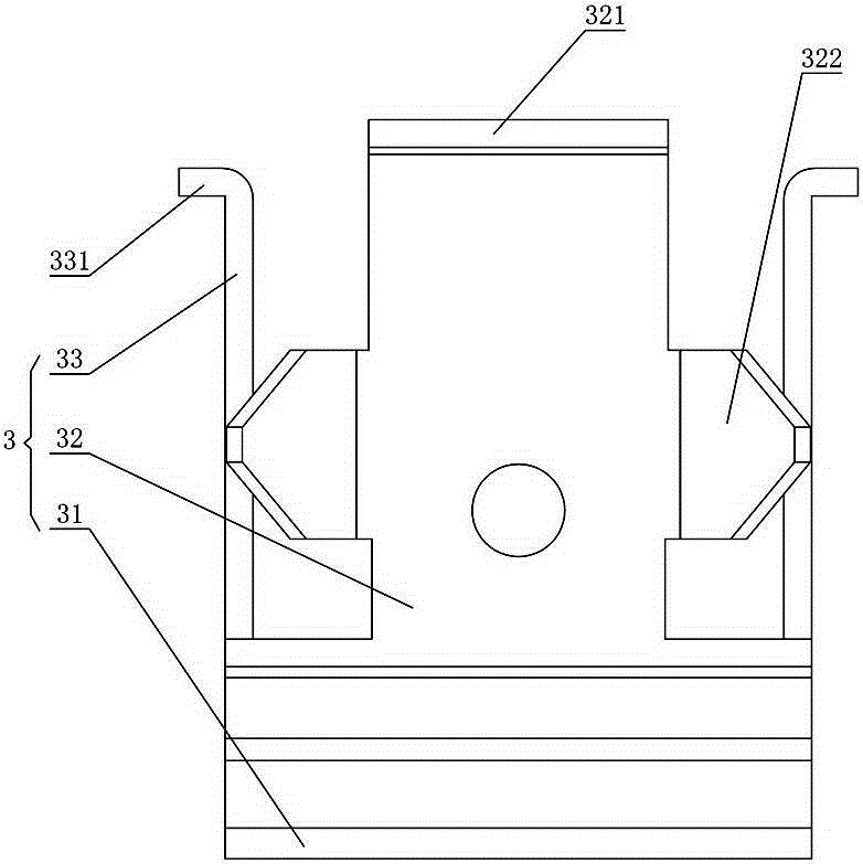
[0032] Figure 1 to Figure 4 Shown is the first embodiment of a guardrail of the present invention, the guardrail includes a surface tube 1, a column 2 and an expansion joint 3, the bottom of the surface tube 1 is provided with a groove 11, and its structure is simple and easy to install. When assembling, Insert one end of the expansion joint 3 into the column 2 first, and connect the expansion joint 3 with the column 2 with the top wire 4 to realize the pre-installation of the expansion joint 3 and the column 2, and then extend the expansion joint 3 The part to the outside of the column 2 is sleeved in the groove 11, and when the top screw 4 is further tightened, the expansion joint 3 expands and simultaneously expands and connects with the inner wall of the column 2 and the inner wall of the groove 11, thereby realizing the surface tube 1 and the column 2 Compared with the traditional direct screw connection, the guardrail is a plug-in structure, that is, the column 2 and th...

Embodiment 2

[0038] Figure 5 to Figure 7 The second embodiment of a guardrail of the present invention is shown, which is basically the same as that of Embodiment 1, the only difference being that both sides of the side plate 32 are bent inwardly with reinforcing ribs 323, and the reinforcing ribs 323 can on the one hand Supporting the inner wall of the column 2, on the other hand, can prevent the side plate 32 from bending and deforming during the jacking process, and improve the stability of the connection. One of the side plates 32 is provided with a positioning hole 324, which is passed through by a fastener The pipe wall of the column 2 is threaded with the positioning hole 324 to facilitate the pre-installation of the expansion joint 3 and the column 2. The other side plate 32 is inclined to the inside of the expansion joint 3, that is, a formation is formed between the side plate 32 and the column 2. There is room for the side plates 32 to expand and deform. When the jacking screw ...

Embodiment 3

[0040] Figure 8 to Figure 11A third embodiment of a guardrail of the present invention is shown, which is basically the same as that of Embodiment 1, the only difference being that the expansion joint 3 includes a bottom plate 31, and side plates 32 are bent on both sides of the bottom plate 31, and the side plates 32 ends are bent with a first expansion plate 321 protruding to the outside of the column 2, and a third expansion plate 325 is bent inward on both sides of one of the side plates 32, and the end of the third expansion plate 325 is bent There is an inwardly inclined jacking plate 326. The jacking screw 4 is threadedly connected with the side plate 32 and passes through the jacking plate 326 to offset the other side plate 32. The structure is simple and the operation is convenient. When the jacking screw 4 is tightened, The lifting plate 326 expands to both sides and drives the two third expansion plates 325 to expand and connect with the inner wall of the column 2,...


PUM


Abstract

The invention discloses a guardrail, which comprises a surface pipe, a column and an expansion joint. The bottom of the surface tube is provided with a groove. The part to the outside of the column is sleeved in the groove, and when the top wire is tightened, the expansion joint expands and simultaneously expands and connects with the inner wall of the column and the inner wall of the groove. The guardrail has the advantages of simple structure, good stability and the ability to realize surface tube post-installation.

Description

Technical field [0001] The present invention mainly involves pipe connection technology, especially a fence. Background technique [0002] In the fields of guardrails, windows, etc., connections need to be implemented between connectors and columns.In existing technologies, generally connect to the connection with the connector after passing through the outer wall of the facial pipe through the fastener. At the same time, the connector is also connected to the column through the fastener. When this structure is connected, the facial tube and the column are both and the columns are all columns.You need to punch the attack, and excessive holes in the surface can affect its mechanical strength. The connecting parts between the facial tube and the pillars need to be accurately located to achieve installation. There is no adjustable space, which greatly affects the installation efficiency, and the connection is at the connection.The force is mainly concentrated on the fastener, and th...

Claims


Application Information

Patent Timeline
Patent Type & Authority Patents(China)
IPC IPC(8): F16B7/00F16B7/18
Inventor 谢斌泉
Owner HUNAN GOLDWELL NEW MATERIALS TECH CO LTD
Why Eureka
Try Eureka