Magnetic force positioning electronic switch

An electronic switch and magnetic technology, which is applied in the field of magnetic positioning electronic switches, can solve problems such as unsafe use, wear or deformation, and gear failure, and achieve the effect of structural science

Inactive Publication Date: 2014-05-14
NANZHANG VOCATIONAL EDUCATION CENT
View PDF0 Cites 0 Cited by
  • Summary
  • Abstract
  • Description
  • Claims
  • Application Information

AI Technical Summary

Problems solved by technology

[0002] The technical structure of the various electronic switches in use today is mechanical, that is, the built-in movable contact is rotated or slid to adjust and the fixed contact forms a path, and the positioning setting is generally carried out by mechanical cards. The gear setting, after a long time of use, will wear or deform, which will directly cause the gear to fail, and it is very unsafe to use

Method used


Image

  • Magnetic force positioning electronic switch

Examples


Embodiment Construction

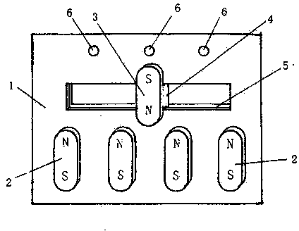
[0012] As shown in the accompanying drawings, one side of the base 1 of an electronic switch is provided with several uniformly distributed magnetic blocks 2, the other side is provided with several switch contacts 6, and a slidable magnetic block 3 is installed in the middle. The magnetic poles of several uniformly distributed fixed magnetic blocks 2 and slidable magnetic blocks 3 are oppositely arranged. The slidable magnetic block 3 is installed in the transverse sliding groove 5 in the middle of the base 1 through the sliding seat 4 provided with contacts below, thereby forming a structure capable of sliding left and right. The set switch contacts 6 are located between two of the fixed magnetic blocks 2 .

[0013] When implementing the present technology, the sliding seat 4 that is provided with the contact can be connected with the electronic components, so that when sliding, the contact can turn on the switch when it slides to the switch contact 6 that needs to be positi...


PUM


Abstract

The present invention provides a magnetic force positioning electronic switch. The magnetic force positioning electronic switch is characterized in that a plurality of magnetic blocks are distributed evenly at one side of a pedestal of an electronic switch, a plurality of switch contacts are arranged at the other side, and a slidable magnetic block is arranged in the center; the magnetic poles of the plurality of evenly distributed fixed magnetic blocks and the slidable magnetic block are inverse, and the slidable magnetic block is arranged in a transverse chute in the middle of the pedestal via a lower sliding base with a contact, thereby forming a structure capable of sliding left and right. When the magnetic force positioning electronic switch is used, the slidable magnetic block can be slide left and right to adjust the gear of the switch. The magnetic poles of the plurality of evenly distributed fixed magnetic blocks and the slidable magnetic block are inverse, and based on a magnetic effect of same-sex repulsion, the slidable magnetic block can be stopped at the needed switch contact automatically and accurately when sliding, so that the gear of the switch can be adjusted very conveniently and accurately under the magnetic effect. The magnetic force positioning electronic switch possesses the characteristics of being accurate and convenient in adjustment, and being safe and durable.

Description

technical field [0001] The invention relates to an electronic switch, in particular to a magnetic positioning electronic switch. Background technique [0002] The technical structure of the various electronic switches in use today is mechanical, that is, the built-in movable contact is rotated or slid to adjust and the fixed contact forms a path, and the positioning setting is generally carried out by mechanical cards. If the position setting is too long, it will be worn or deformed, which will directly cause the gear to fail, and it is very unsafe to use. Contents of the invention [0003] The object of the present invention is to provide a magnetic force positioning electronic switch, which can position its switch contacts through magnetic force, which is accurate, safe and extremely convenient to operate. [0004] The invention includes a fixed magnetic block and a slidable magnetic block. The adopted technical solution is: on one side of the base of an electronic ...

Claims


Application Information

Patent Timeline
Patent Type & Authority Applications(China)
IPC IPC(8): H01H36/00
Inventor 尚志一尚有根
Owner NANZHANG VOCATIONAL EDUCATION CENT
Why Eureka
Try Eureka