a pressure reducing valve

A pressure reducing valve and valve body technology, which is applied in the field of pressure reducing valves, can solve the problems of short spring life, high frequency of maintenance and replacement, poor system safety, etc., and achieve the effect of avoiding fatigue and solving the failure of pressure reducing valves

Active Publication Date: 2017-01-18
SHANGHAI AVECO VALVE CO LTD
View PDF6 Cites 0 Cited by
  • Summary
  • Abstract
  • Description
  • Claims
  • Application Information

AI Technical Summary

Problems solved by technology

[0003] The purpose of the present invention is to provide an improved pressure reducing valve, which can overcome the disadvantages of short spring life, high maintenance and replacement frequency, poor system safety and high operating cost in the prior art.

Method used


Image

  • a pressure reducing valve
  • a pressure reducing valve

Examples


Embodiment Construction

[0009] The present invention will be further described below in conjunction with the accompanying drawings and embodiments.

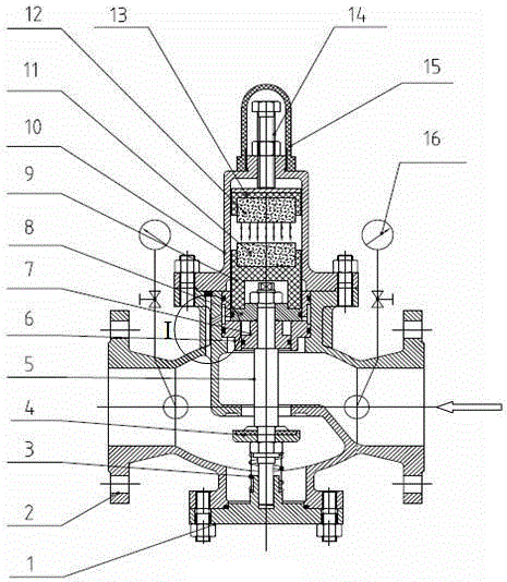
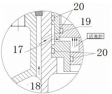
[0010] In the accompanying drawings, the symbols indicated by the symbols are as follows: 1 bottom cover, 2 valve body, 3 spring, 4 valve flap, 5 valve stem, 6 piston cylinder, 7 lower piston, 8 upper piston, 9 lower magnet bushing, 10 valve Cover, 11 lower magnet, 12 upper magnet, 13 upper magnet bushing, 14 adjusting bolt, 15 bonnet, 16 pressure gauge parts, 17 horizontal hole, 18 straight through hole, 19 annular groove, 20 O-ring.

[0011] A pressure reducing valve according to the present invention mainly includes a valve body and a valve cover connected with the valve body. One end of the component is arranged above the piston, and the other end is connected with the adjusting bolt. The magnetic component includes upper and lower magnet bushings and upper and lower magnet bushings that are arranged in the upper and lower magnet bushings and match ...


PUM


Abstract

The invention relates to a pressure reducing valve for a water system. The pressure reducing valve mainly comprises a valve body, and a valve cover connected with the valve body. The pressure reducing valve is characterized in that a magnetic force part, a piston and an adjusting bolt are arranged in the valve cover; one end of the magnetic force part is arranged above the piston, and the other end is connected with the adjusting bolt; the magnetic force part comprises upper and lower magnet bushings, and upper and lower magnetic columns arranged in the upper and lower magnet bushings and fitting the upper and lower magnet bushings; the lower magnet bushing is positioned above the piston; the upper magnet bushing is contacted with the adjusting bolt through a metal washer; a thread hole is formed in the upper part of the valve cover; and the adjusting bolt is positioned in the thread hole, and is fixedly connected with the valve cover. As the magnetic force among magnets is permanent, continuous and adjustable, the fatigue and rupture phenomenon of the spring for long-time use in a traditional mode is prevented, and the problem of failure of the pressure reducing valve caused by the faults of the spring is solved. The pressure reducing valve improves the system operation safety, and largely saves the maintenance cost.

Description

technical field [0001] The invention relates to the technical field of valve bodies, in particular to a pressure reducing valve for water systems. Background technique [0002] Currently, the existing pressure reducing valve structures used in water systems are generally spring-piston structures or spring-diaphragm structures. Springs play a very important role in the performance of pressure reducing valves. The manufacture of the spring is also quite complicated. It not only requires the material to have high fatigue limit, yield point, sufficient impact toughness, excellent hardenability, low overheat sensitivity and not easy to decarburize, but also must have good performance. Guaranteed heat treatment process. Therefore the manufacture of spring has higher difficulty, and quality and service life are difficult to guarantee. And the spring is under the action of alternating stress for a long time, and its rigidity and other mechanical properties will inevitably decline...

Claims


Application Information

Patent Timeline
Patent Type & Authority Patents(China)
IPC IPC(8): F16K31/363F16K31/08
CPCF16K17/20F16K31/086F16K31/363
Inventor 陈建銮周进超张正春
Owner SHANGHAI AVECO VALVE CO LTD
Why Eureka
Try Eureka