
Electromigration Test Structure

A technology for testing structure and electromigration, which is applied in the direction of measuring electricity, measuring devices, measuring electrical variables, etc., and can solve problems such as short-circuit failure of metal wire layers

Active Publication Date: 2016-07-06
SEMICON MFG INT (SHANGHAI) CORP
View PDF7 Cites 0 Cited by
  • Summary
  • Abstract
  • Description
  • Claims
  • Application Information

AI Technical Summary

Problems solved by technology

[0005] In view of this, the present invention provides an electromigration test structure to solve the problem that the existing electromigration test structure cannot measure short-circuit failure with the adjacent metal line layer

Method used


Image

  • Electromigration Test Structure
  • Electromigration Test Structure
  • Electromigration Test Structure

Examples


Embodiment Construction

[0017] In order to make the purpose, technical solution and advantages of the present invention more clear, the present invention will be further described in detail below with reference to the accompanying drawings and examples.

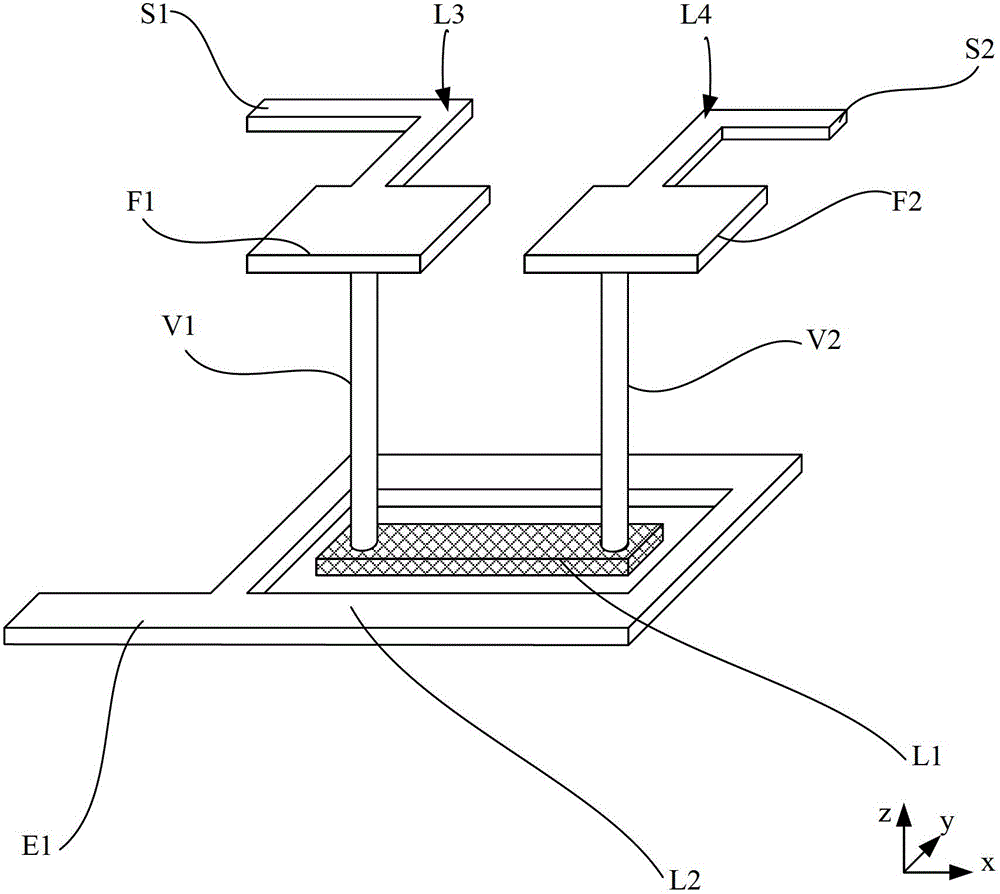
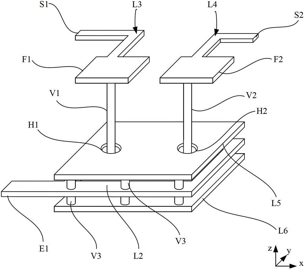
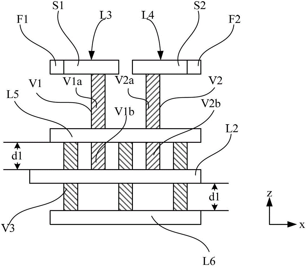
[0018] like figure 2 and image 3 shown, combined with figure 1 , the present invention provides an electromigration test structure, comprising:

[0019] The tested wire L1 and the first short-circuit monitoring wire L2 located on the first wiring layer, and the two detection wires L3 and L4 located on the second wiring layer above the first wiring layer;

[0020] The detection wire L3 includes a current terminal S1 and a voltage terminal F1, and the detection wire L3 is electrically connected to the tested wire L1 through a first contact hole V1; the detection wire L4 includes a current terminal S2 and a voltage terminal F2, and the detection wire L4 passes through another The first contact hole V2 is electrically connected to the tested wire; ...


PUM


Abstract

The invention provides an electromigration test structure. One the basis of an existing electromigration test structure, two monitoring wires are formed at wiring layers with a predetermined distance at upper and lower surfaces of a tested conductive wire, and the monitoring wires are used for monitoring and measuring the short circuit failure caused by a projection formed by electromigration in a height direction.

Description

technical field [0001] The invention relates to the field of semiconductor devices, in particular to an electromigration test structure. Background technique [0002] Electromigration is a species transfer phenomenon due to the stepwise motion of ions in a conductor, which results from the transfer of momentum between conducting electrons and diffusing metal atoms. When electromigration occurs, part of the momentum of a moving electron is transferred to a nearby activated ion, which causes the ion to leave its original position. When the current density is high, the electrons move from the cathode to the anode under the force of the electrostatic field to form an electron wind, which will cause a large number of atoms to move away from their original positions. Over time, electromigration can lead to cracks or nicks in conductors, especially narrow wires, that prevent the flow of electricity. This defect is called a void or internal failure, or open circuit. Electromigrati...

Claims


Application Information

Patent Timeline
Patent Type & Authority Patents(China)
IPC IPC(8): G01R31/02
Inventor 王笃林郑雅文胡永锋陆黎明
Owner SEMICON MFG INT (SHANGHAI) CORP
Learn More