Optical fibre distribution frame and wiring method in optical fibre distribution frame

A technology of an optical fiber distribution frame and a wiring method, which is applied in the field of optical fiber communication, can solve the problems of an increase in the number of optical fibers and jumpers of optical cables, inconvenient operation, and complicated wiring and fiber routing, so as to solve the problem of wiring management and facilitate maintenance. And the effect of managing and enriching application functions

Active Publication Date: 2014-05-21
SHENZHEN EPLU SCI TECH
View PDF5 Cites 6 Cited by
  • Summary
  • Abstract
  • Description
  • Claims
  • Application Information

AI Technical Summary

Problems solved by technology

However, most of the optical fiber distribution frames using light with such a small radius of curvature are in the research and development stage; in addition, the increase in the capacity of the optical fiber unit box will greatly increase the number of optical fiber cables and jumper fibers, resulting in more dense and complex wiring and fiber routing. , which brings inconvenience to the operation
[0003] The traditional optical fiber distribution frame is generally operated on one side, with single function, small capacity and low density; in addition, the fiber jumper between the racks needs to pass through the fiber rack at the top of the machine room, and a large amount of space needs to be reserved in the rack It is used to store redundant fiber jumpers, and the production cost is high; moreover, this kind of fiber distribution frame has complex fiber jumper wiring and many crossovers, which brings inconvenience to installation, maintenance and management

Method used


Image

  • Optical fibre distribution frame and wiring method in optical fibre distribution frame
  • Optical fibre distribution frame and wiring method in optical fibre distribution frame
  • Optical fibre distribution frame and wiring method in optical fibre distribution frame

Examples


Embodiment Construction

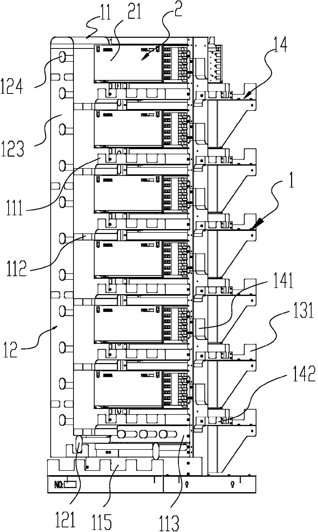
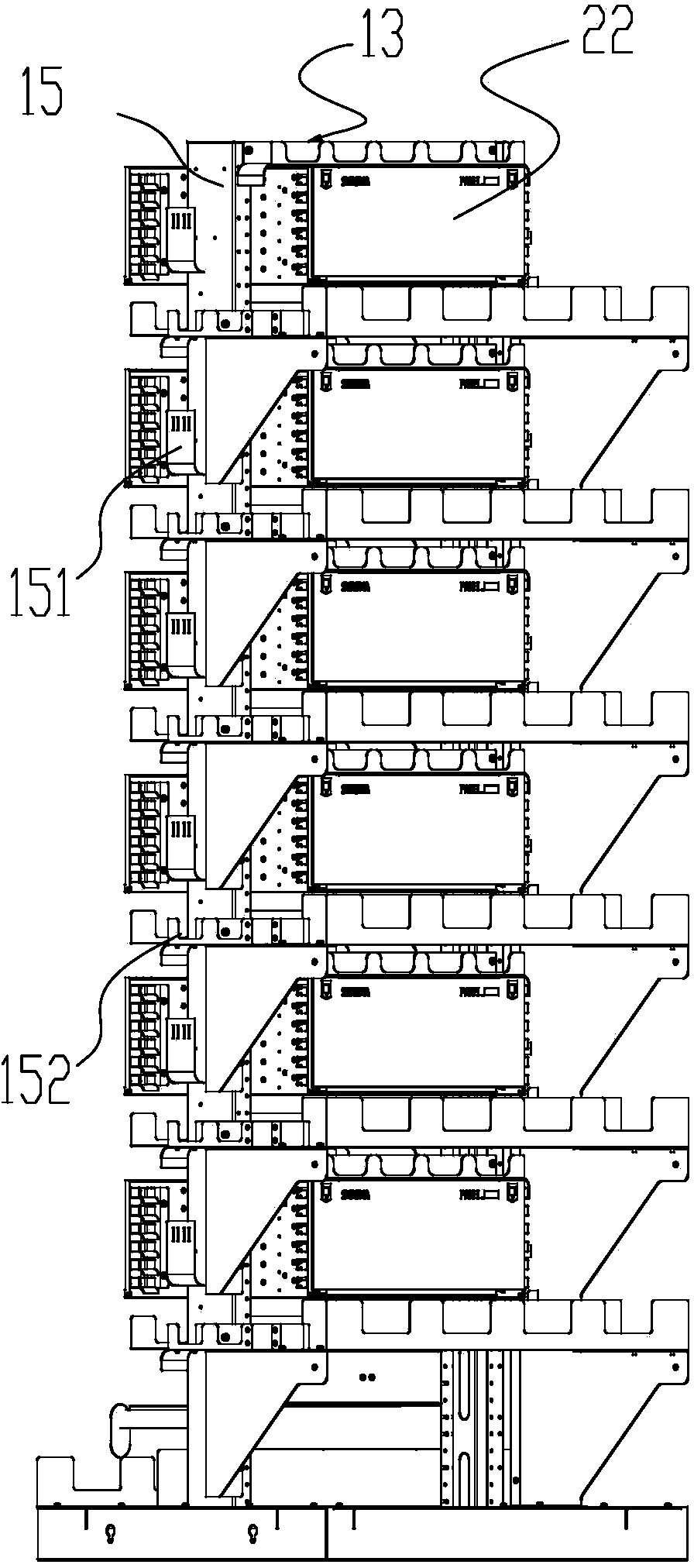
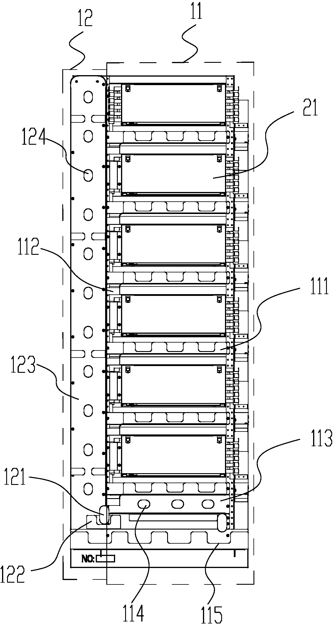
[0044]The optical fiber distribution frame in the prior art generally adopts single-sided operation, simple function, and small capacity, and the inter-rack fiber is routed through the fiber routing frame on the top of the machine room, which takes up a large space and high cost; in addition, the optical fiber distribution frame The internal fiber jumper wiring is complex and has many crossovers, which is not conducive to maintenance and management. In order to solve the above-mentioned defects existing in the prior art, the main innovation of the present invention is: by separately separating the end surface of the optical cable from the fiber jumper operation surface, the rack can be operated on both sides to realize functional partitioning, so that the rack The management is clearer; racks are equipped with dedicated horizontal channels and front and rear fiber routing channels for fiber jumping between racks, so that fiber jumping between racks does not need to be routed th...


PUM


Abstract

The invention relates to an optical fibre distribution frame. The optical fibre distribution frame comprises a rack, wherein the rack comprises a jump fibre operation surface, a jump fibre storage side, an optical cable end-forming surface, an optical cable lead-in side, and a front-and-rear fibre feeding side; the jump fibre operation surface and the optical cable end-forming surface are oppositely arranged at the both sides of the rack; a plurality of second inter-frame jump fibre horizontal fibre-feeding grooves for providing a horizontal routing channel for the inter-frame jump fibres are formed in the optical cable end-forming surface, and the second inter-frame jump fibre horizontal fibre-feeding grooves are distributed at intervals along the longitudinal direction of the rack; a plurality of front-and-rear fibre feeding grooves for the feeding of inter-frame jump fibres along the front-and-rear direction of the rack are arranged in the front-and-rear fibre feeding side at intervals; thus when the inter-frame jump fibres arrive at one side of the optical cable end-forming surface through the front-and-rear fibre feeding grooves, fibre feeding is carried out by the second inter-frame jump fibre horizontal fibre-feeding grooves of the adjacent optical fibre distribution frames to realize inter-frame fibre jumping.

Description

technical field [0001] The invention relates to the field of optical fiber communication, more specifically, to an optical fiber distribution frame and a wiring method in the optical fiber distribution frame. Background technique [0002] With the development of FTTX, the number of optical fibers in the computer room is continuously increasing, and higher requirements are placed on the manageability of fiber jumpers, which makes the use of traditional optical distribution frames (Optical Distribution Frame, ODF) a great challenge. . At the same time, with the increasing shortage of computer room land, the expensive use of space in the computer room also puts forward better capacity requirements for optical fiber distribution frames. The appearance of optical fibers with small curvature radius provides convenience for further increasing the capacity of optical distribution frames. However, most of the optical fiber distribution frames using light with such a small radius of...

Claims


Application Information

Patent Timeline
Patent Type & Authority Applications(China)
IPC IPC(8): G02B6/44
Inventor 李中勋邵海波朱雪锋刘灿胜
Owner SHENZHEN EPLU SCI TECH
Why Eureka
Try Eureka