
Method and device for optimal division of tracking area

A tracking area and tracking area update technology, applied in the field of network optimization, can solve problems such as inability to model users, incompatibility, and inability to reflect, and achieve good engineering application value and ensure accuracy.

Active Publication Date: 2017-04-19
GUANGDONG PLANNING & DESIGNING INST OF TELECOMM
View PDF6 Cites 0 Cited by
  • Summary
  • Abstract
  • Description
  • Claims
  • Application Information

AI Technical Summary

Problems solved by technology

[0008] The self-organizing TA List partition algorithm based on the motion model, its main feature is to use the Markov chain to predict the mobile trend of the UE. After obtaining a preliminary TA List, it is gradually optimized and updated. It uses Markov The chain needs to know in advance the transition probability of the user's specific state at each step. This is assumed in the model that the user is known, but this is not consistent with the reality, so that it cannot completely model the user's movement reasonably. Moreover, the TA planning itself is gradual, and the user's movement gradually improves over time. In practice, the user's movement will change the overall number of users in the TA and the user's paging volume, and the Markov chain is directly used to build model, does not reflect this change
The TA planning method based on the graph partition model models the TA partition problem as a graph partition problem, which will bring a large amount of calculation, and the calculation complexity is too large, so that it cannot directly guide the engineering design work

Method used

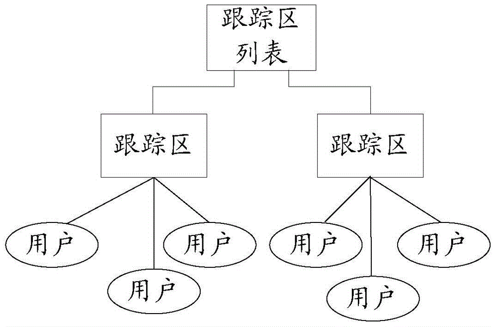
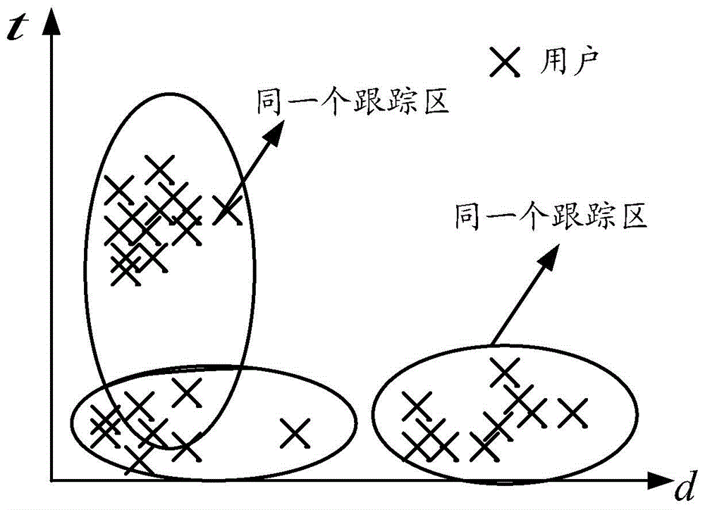

Image

  • Method and device for optimal division of tracking area
  • Method and device for optimal division of tracking area
  • Method and device for optimal division of tracking area

Examples


Embodiment Construction

[0028] In order to make the object, technical solution and advantages of the present invention clearer, the present invention will be further described in detail below in conjunction with the accompanying drawings and embodiments. It should be understood that the specific embodiments described here are only used to explain the present invention, and do not limit the protection scope of the present invention.

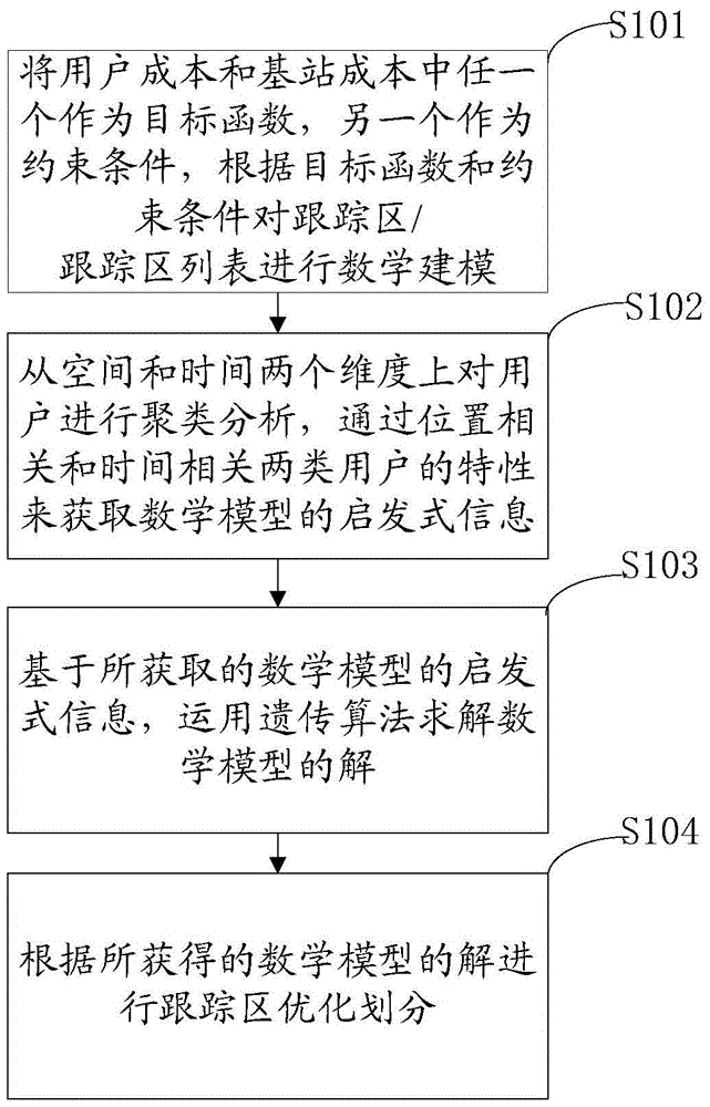
[0029] In one embodiment, the tracking area optimal division method, such as figure 2 As shown, the method includes:

[0030] Step S101: Take any one of the user cost and the base station cost as an objective function, and the other as a constraint condition, and mathematically model the tracking area / tracking area list according to the objective function and constraint conditions, and the user cost includes the tracking area update Cost and paging cost, the cost of the base station includes the cost of reconfiguration of the tracking area;

[0031] Step S102: Perform...


PUM


Abstract

The invention discloses an optimized tracking area partition method and device. According to the method, either user cost or base station cost is taken as an objective function, the other is taken as the constraint condition, and mathematic modeling is conducted on a tracking area / tracking area list according to the objective function and the constraint condition; clustering analysis is conducted on a user from the spatial dimension and the time dimension, and heuristic information of a mathematical model is acquired through two user characteristics which are location correlation and time correlation; the solution of the mathematical model is solved with the genetic algorithm; finally, optimized tracking area partition is conducted according to the acquired solution of the mathematical model. According to the method and device, equilibrium among paging cost, tracking area updating cost and tracking area reconstruction cost is achieved; prediction clustering analysis is conducted on the user to enable the acquired result to be more close to reality, and engineering application value is high; the optimal solution of the mathematically model can be solved fast with the genetic algorithm, the accuracy of the solution is ensured at the same time, and therefore the method and device are suitable for practical application.

Description

technical field [0001] The present invention relates to the technical field of network optimization, in particular to a tracking area optimal division method and device. Background technique [0002] With the issuance of commercial licenses for 4G LTE networks in China, the planning and construction of TD-LTE networks has been in full swing. In the TD-LTE network, the data business service is expected to increase significantly, and at the same time, more emphasis is placed on user mobility management and service quality. All these make the design and optimization of 4G LTE mobile communication network system face great challenges. [0003] Similar to the concept of Location Area (LA) / Routing Area (RA) in 3G, Tracking Area (TA) is a concept introduced by the core network in LTE network and belongs to User Equipment (UserEquipment, UE ) The smallest particle of roaming, which is used for the tracking and quick paging management of the UE by the Mobility Management Entuty (MM...

Claims


Application Information

Patent Timeline
Patent Type & Authority Patents(China)
IPC IPC(8): G06F17/30
CPCG06Q10/04G06Q50/30
Inventor 杨超肖恒辉李炯城陈运动赖志坚
Owner GUANGDONG PLANNING & DESIGNING INST OF TELECOMM
Learn More