Pressure cooker with functions of preventing splashing and collecting oil and water

A pressure cooker and anti-splash technology, which is applied in the field of pressure cookers, can solve the problems of increasing the exhaust pressure of pressure cookers, which is not conducive to the safe use of pressure cookers, and is not easy to be popularized and applied due to safe use.

Inactive Publication Date: 2014-06-04
戴永锋
View PDF15 Cites 0 Cited by
  • Summary
  • Abstract
  • Description
  • Claims
  • Application Information

AI Technical Summary

Problems solved by technology

In the latter technical solution, the oil and water gathered around the bonnet are sprayed out from the air duct connected to the upper part of the muffler cover, which makes it easier to increase the exhaust pressure of the pressure cooker, especially when there is an abnormal state in which the air duct is blocked, it will significantly increase The exhaust pressure of the pressure cooker is extremely unfavorable to the safe use of the pressure cooker, and the application of this technical solution has certain dangers
[0006] In a word, the existing technical solutions are not easy to popularize and apply because of the use defects or potential use safety problems, so that the existing pressure cookers are prone to problems in the cooking process and cannot be properly solved.

Method used


Image

  • Pressure cooker with functions of preventing splashing and collecting oil and water
  • Pressure cooker with functions of preventing splashing and collecting oil and water
  • Pressure cooker with functions of preventing splashing and collecting oil and water

Examples


Embodiment 1

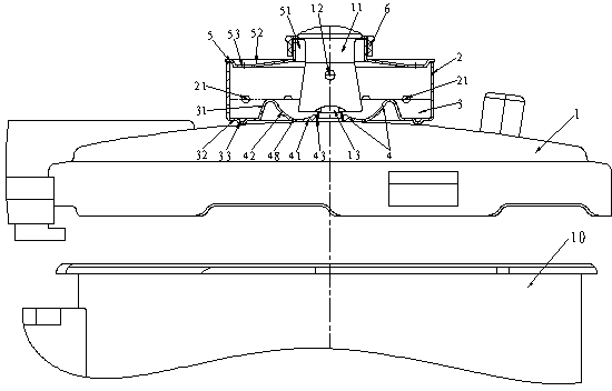
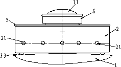
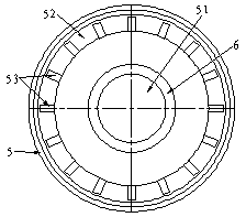
[0031] The pressure cooker with the function of preventing splash and collecting oil and water according to Embodiment 1 of the present invention (for the structure see Figure 1 to Figure 4), including a pot body 10 of a pressure cooker and a matching pot cover 1 with a pressure limiting valve, the pot cover 1 has a cylinder around the pressure limiting valve to block the mixed fluid sprayed from the pressure limiting valve The cover 2 is characterized in that: the lower part of the cylinder cover 2 is provided with a receiving groove 3 on the pot cover 1 around the pressure limiting valve bonnet 11; the receiving groove 3 consists of the side wall of the cylinder cover 2 and the inner circumference The inner ring wall 31 and the groove bottom 32 integrally connected between the bottom ends of the two constitute three components; there is an appropriate distance between the cylinder cover 2 and the bonnet 11, and its inner side is provided with a bonnet located below the bonne...

Embodiment 2

[0047] The pressure cooker with the function of preventing splash and collecting oil and water according to the second embodiment of the present invention (for the structure see Figure 5 to Figure 8 ). On the basis of Embodiment 1 of the present invention, the structure difference of Embodiment 2 lies in:

[0048] The above-mentioned pan bottom 41 and the pot cover 1 are integrally constructed.


PUM


Abstract

The invention provides a pressure cooker with the functions of preventing splashing and collecting oil and water. The pressure cooker comprises a cooker body, a cooker cover and a cylindrical cover (2), wherein a receiving groove (3) is formed in the lower portion of the cylindrical cover (2); the receiving groove (3) is composed of the cylindrical cover (2), an inner ring wall (31) and a groove bottom (32); the inner periphery of the inner ring wall (31) is provided with a drainage sleeve plate (4) located below a valve bonnet (11); the drainage sleeve plate (4) is composed of a plate bottom (41) and an inclined wall (42), the outer periphery of the plate bottom (41) is sleeved with the inclined wall (42), the inclined wall (42) is raised upwards in an inclined mode, and the upper circumferential edge of the inclined wall (42) and the upper circumferential edge of the inner ring wall (31) are in butt joint integrally to form a common upper circumferential edge which is lower than the lower edge of a bonnet hole (12). The pressure cooker has the functions of preventing splashing, collecting the oil and the water and reducing noise, is safer to use, can bring convenience to cooking, and has popularization and application value.

Description

technical field [0001] The invention relates to a pressure cooker for cooking, in particular to a pressure cooker with functions of preventing splash and collecting oil and water. Background technique [0002] The cooking pressure cooker (hereinafter referred to as: pressure cooker) that the public uses on the gas range or induction cooker daily, for safety needs, the pot cover of pressure cooker is provided with gravity-type pressure-limiting exhaust valve (hereinafter referred to as: pressure-limiting valve). When the pressure cooker exhausts under pressure limitation, most of the gas is ejected from the four vent holes (hereinafter referred to as: cap holes) on the gravity cap (hereinafter referred to as: valve cap) of the pressure limiting valve, and the following inconveniences are prone to occur: 1. The hot gas mixed with oil, water and fine food particles (hereinafter collectively referred to as: mixed fluid) sprayed out along the horizontal direction is easy to splas...

Claims


Application Information

Patent Timeline
Patent Type & Authority Applications(China)
IPC IPC(8): A47J27/08A47J27/09A47J36/38
Inventor 戴永锋
Owner 戴永锋
Why Eureka
Try Eureka