Moving type hangar

A mobile and hangar technology, applied in the field of mobile hangars, can solve the problems of inability to change and change the hangar, high production cost, limited design space, etc., achieve simple and reliable manufacturing process, reduce the difficulty of erection, and reduce the effect of self-weight

Inactive Publication Date: 2014-06-11
北京云创太和科技有限公司
View PDF6 Cites 6 Cited by
  • Summary
  • Abstract
  • Description
  • Claims
  • Application Information

AI Technical Summary

Problems solved by technology

Although reinforced concrete hangars with steel structures are mature in technology, strong in stability, and high in reliability, they are expensive to manufacture and have a long construction period, and they are all permanent buildings, so the location of the hangar cannot be changed with changes in the external environment
Although the U.S. military's metal struts combined with polymer membrane skin can move freely to a certain extent, the structure of the hangar is limited by mechanical principles, the design space is limited, and the erection process is extremely complicated.

Method used


Image

  • Moving type hangar
  • Moving type hangar
  • Moving type hangar

Examples


Embodiment 1

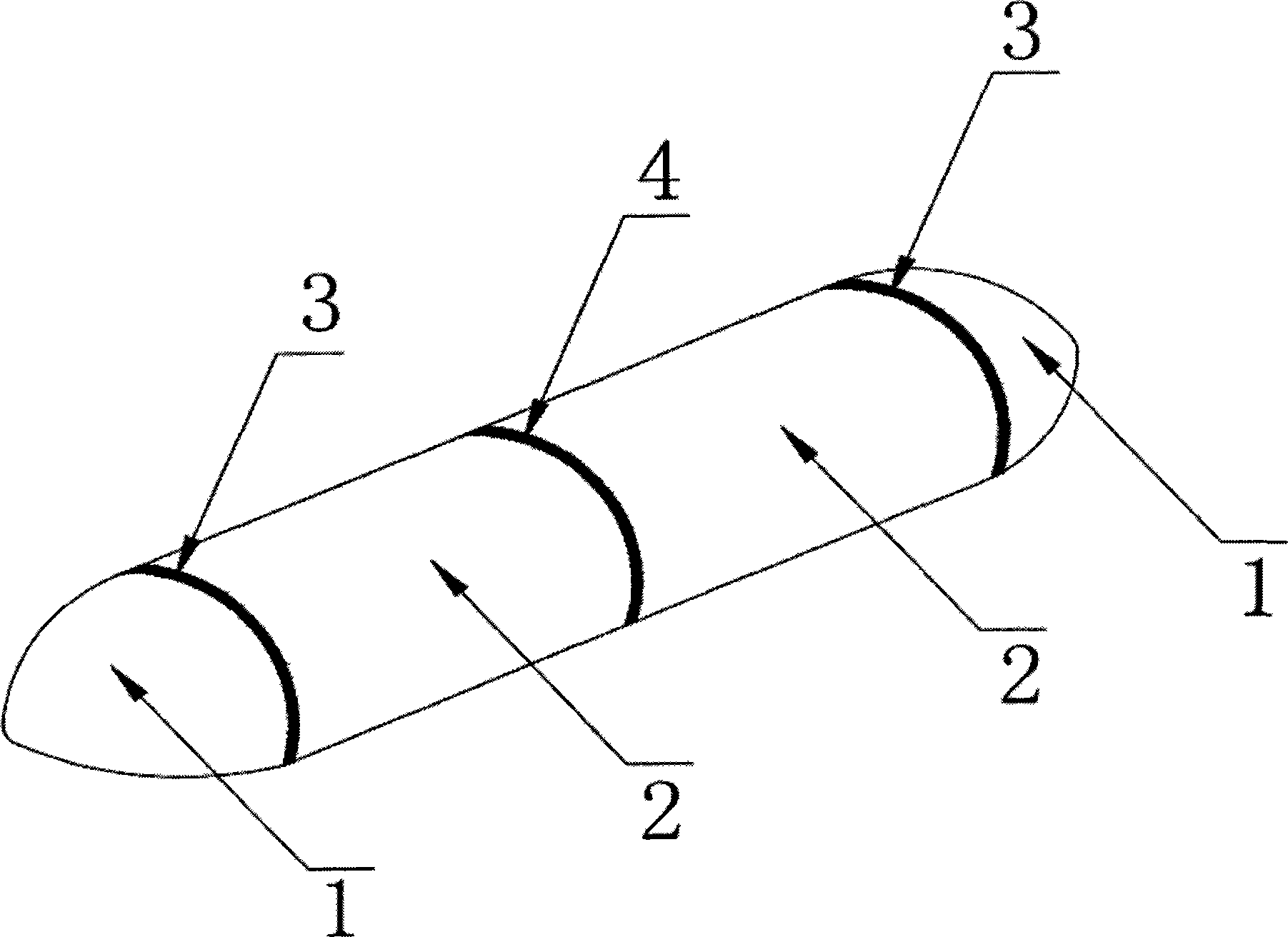
[0039] Such as figure 1 It is a schematic diagram of the main structure of the mobile hangar including two sets of intermediate bodies 2 , including end doors 1 and two sets of intermediate bodies 2 distributed at both ends of the hangar. Among them, 4 is the connection area where the two groups of intermediate bodies are connected to each other through the standard interfaces distributed at their ends, and 3 is the connection area where the end door is connected to the standard interface of the middle body through the special interface on the upper edge of the end door covering tarpaulin.

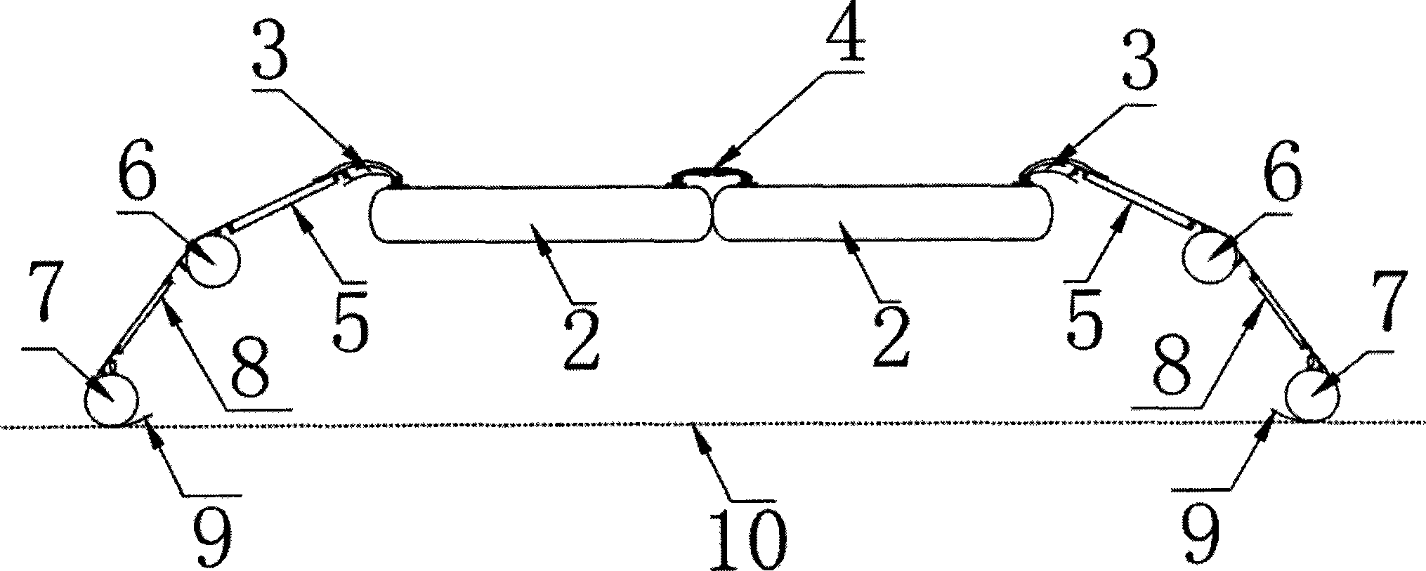
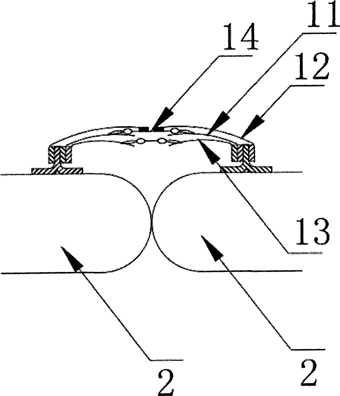
[0040] Such as figure 2 It is a schematic diagram of the longitudinal section of the mobile hangar including two sets of intermediate bodies. It includes 2 sets of middle bodies 2 and two sets of end doors, 4 is the connection area between the middle bodies, 3 is the connection area between the end doors and the middle body, and 5 is the limit of the opening device for the upper half of ...

Embodiment 2

[0047] In this embodiment, using the same manufacturing process and materials, the middle part of the hangar is designed as three sets of intermediate bodies connected to each other, and the hangar as a whole includes end doors distributed at two ends and three sets of intermediate bodies. Such as Figure 7 It is a schematic diagram of the longitudinal section of the hangar in this embodiment.

Embodiment 3

[0049] In this embodiment, using the same manufacturing process and materials, the middle part of the hangar is designed as four sets of intermediate bodies connected to each other, and the hangar as a whole includes end doors distributed at two ends and four sets of intermediate bodies. Such as Figure 8 It is a schematic diagram of the longitudinal section of the hangar in this embodiment.


PUM


Abstract

The invention discloses a moving type hangar, which comprises three parts of end doors, a middle main body and an accessory. The main structure of the moving type hangar disclosed by the invention adopts the modular design; the whole hanger comprises end door modules distributed on two ends of the hangar, and multiple groups of middle main body modules, wherein the end of each group of module is provided with a port; except that the end door position is fixed, the rest modules of the hangar can be subjected to unordered mutual connection. The manufacture material of the main structure of the moving type hangar is selected from one or multiple types of PVC (polyvinyl chloride) membrane material, TPU (thermoplastic urethanes) membrane material, EVA (ethylene vinyl-acetate) membrane material, acrylic ester membrane material, neoprene membrane material, butadiene styrene rubber membrane material, ETFE (ethyl tetra fluoro ethylene) membrane material, PVDF (polyvinylidene fluoride) membrane material, PTFE (polytetrafluoroethylene) membrane material and PVF (polyvinyl fluoride) membrane material. The moving type hangar is erected with an inflation method, each group of modules can be respectively curly packaged after venting, and the moving type hangar has the advantages of strong maneuverability, simple operation process, stable and reliable performance, advanced technical index, scientific structural design, cheap and abundant raw materials and mature manufacture technology and is suitable to popularize and apply within a large range in the industry.

Description

technical field [0001] The invention relates to a mobile hangar, in particular to a mobile hangar with an air film structure. Background technique [0002] Under long-term open-air parking conditions, natural factors such as ultraviolet rays, acid rain, and oxygen will cause damage to the aircraft to a certain extent, which will greatly shorten the calendar life of the aircraft. In severe cases, even before the fatigue life of the aircraft, its calendar life has expired, forcing the aircraft to retire or be scrapped in advance. [0003] In the field of civil aviation, in order to improve economic benefits, major airlines generally adopt the method of increasing the flight frequency of aircraft, improving the efficiency of aircraft use, reducing the number of aircraft purchased, and controlling funding and overall operating costs. In the state of high-load operation, in addition to the necessary ground maintenance and maintenance, the time in standby state is relatively shor...

Claims


Application Information

Patent Timeline
Patent Type & Authority Applications(China)
IPC IPC(8): E04H6/44
Inventor 刘云鹏孔庆钢朱阳春
Owner 北京云创太和科技有限公司
Why Eureka
Try Eureka