Power line connecting structure of stator

A technology for power lines and stators, which is applied in the field of construction of connecting power lines, can solve problems such as difficulty in ensuring creepage, spatial distance, and complex connection structures, and achieves the effects of high degree of freedom, improved reliability, and creepage assurance.

Active Publication Date: 2014-06-11
SANYO DENKI CO LTD
View PDF8 Cites 0 Cited by
  • Summary
  • Abstract
  • Description
  • Claims
  • Application Information

AI Technical Summary

Problems solved by technology

Therefore, the creepage and space distance of electrical insulation are restricted by the interval of the pattern, and it is difficult to ensure the creepage and space distance stipulated by safety standards, etc.
[0016] In addition, in the technique of Patent Document 1, a divided substrate is used instead of the connector, so the cost can be reduced, and connection defects can be eliminated by coupling and fixing, but the connection structure is complicated

Method used


Image

  • Power line connecting structure of stator
  • Power line connecting structure of stator
  • Power line connecting structure of stator

Examples


Embodiment approach 1

[0039] The power line connection structures of Embodiments 1 and 2 are structures in which lead wires serving as power lines are connected to a wiring board included in a stator.

[0040] In the power line connection structure of Embodiment 1, the core wire of the lead wire is arranged in the lead-in terminal that can be reduced in diameter coupled with the pad of the wiring board, and the cover part and the core wire of the lead wire are crimped after the lead-in terminal is crimped. In the state, connect the core wire of the lead wire to the lead-in terminal.

[0041] In the power line connection structure of Embodiment 2, the insertion terminal coupled with the lead wire is arranged in the lead-in terminal coupled to the pad of the wiring board, and the lead-in terminal is crimped in a state where the lead-in terminal is crimped. Next, combine the insertion terminal of the lead wire with the lead-in terminal.

[0042] According to the structure of Embodiment 1 and Embodime...

Embodiment approach 1

[0044]

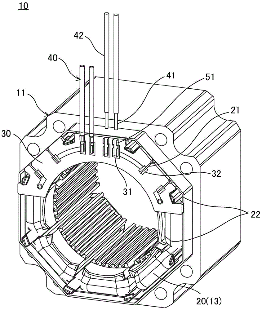
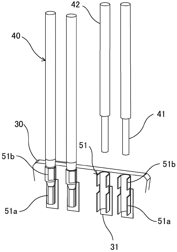
[0045] First, refer to figure 1 and figure 2 The power line connection structure of the stator according to Embodiment 1 will be described. figure 1 It is a perspective view of the power line connection structure of the stator of Embodiment 1. figure 2 yes figure 1 An enlarged view of the main part.

[0046] Such as figure 1 As shown, for example, a stator core 11 of a stator 10 of a stepping motor has a plurality of pole teeth 13 . Insulated electric wires 21 such as enameled wires, for example, are wound around the pole teeth 13 to form a plurality of coils 20 . The poles of the coil 20 are connected by jumper wires 22 to form the respective phases of the motor. The winding start or end of the insulating film electric wire 21 of each phase coil 20 is connected to the power line 40 from the power source on the wiring board 30 .

[0047] As the wiring board 30 of this embodiment, for example, a printed wiring board with a wiring pattern formed by a photolit...

Embodiment approach 2

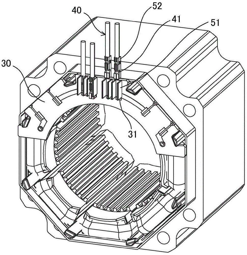
[0068] Next, refer to image 3 and Figure 4 The power line connection structure of the stator according to Embodiment 2 will be described. image 3 It is a perspective view of the power line connection structure of the stator of Embodiment 2. Figure 4 yes image 3 An enlarged view of the main part.

[0069] Such as image 3 As shown, the power line connection structure of the stator according to Embodiment 2 is different from Embodiment 1 in that the covering part of the lead wire 40 is crimped on the lead-in terminal 51 and the insertion terminal 52 is crimped on the core wire 41 to perform crimping. combined.

[0070] That is, in the power line connection structure of the stator according to Embodiment 2, the lead-in terminals 51 that can be reduced in diameter by a pressing device such as a crimping machine are bonded to the power line connection pads 31 of the wiring board 30 . On the other hand, an insertion terminal 52 is coupled to the covering portion of the le...


PUM


Abstract

The invention relates to a power line connecting structure of a stator. A simple structure which improves reliability of connection and secures creeping and spatial distances for electrical insulation without increasing manufacturing cost is provided. Feed-through terminals (51) whose diameters can be reduced are bonded to lands (31) of a wiring substrate (30), and insertion terminals are bonded to core wires (41) of lead wires (40). The insertion terminals of the lead wires (40) are arranged in the feed-through terminals (51) bonded to the lands (31). In a state where the feed-through terminals (51) are swaged and the insertion terminals (52) of the lead wires (40) are pressure-bonded, the insertion terminals (52) of the lead wires (40) are bonded to the feed-through terminals (51).

Description

technical field [0001] The present invention relates to a structure in which power lines are connected to a wiring board included in a stator of a motor. Background technique [0002] The winding start or end of the insulation-coated electric wire of the coil wound on the stator core of the electric motor is connected to the electric power line from the power supply via a printed wiring board. [0003] As the electric power line, a lead wire in which a core wire such as a copper wire is covered with a cylindrical electrical insulating material is generally used. The structure of connecting the leads to the printed wiring board includes a structure of directly connecting the leads to the printed wiring board and a structure of indirectly connecting the leads to the printed wiring board via a connector. [0004] In the structure where the lead wire is directly connected to the printed wiring board, the core wire of the lead wire is directly inserted into the through hole prov...

Claims


Application Information

Patent Timeline
Patent Type & Authority Applications(China)
IPC IPC(8): H02K3/50
CPCH02K2203/06H02K3/50H02K3/522H02K5/225H02K2203/09
Inventor 三浦幸夫内山和良依田和弘
Owner SANYO DENKI CO LTD
Why Eureka
Try Eureka