Novel rotor brake mechanism

A technology of brake mechanism and rotor, applied in electromechanical devices, control mechanical energy, electrical components, etc., can solve the problem of motor occupying a large space and occupying a large area.

Inactive Publication Date: 2014-06-11
ZHEJIANG LINIX MOTOR
View PDF6 Cites 0 Cited by
  • Summary
  • Abstract
  • Description
  • Claims
  • Application Information

AI Technical Summary

Problems solved by technology

[0002] There is no brake mechanism inside the existing motor, and the brake is realized by the external auxiliary mechanism, which causes the motor to take up a lot of space when it is used. Even if the motor is small, it will occupy a large area due to the supporting equipment. Therefore, a belt with The motor of the brake structure is very necessary

Method used


Image

  • Novel rotor brake mechanism

Examples


Embodiment Construction

[0009] Below in conjunction with accompanying drawing, the present invention will be further described:

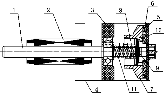
[0010] The new rotor brake mechanism includes motor housing 4, end cover 3, rotor 2, stator and rotor shaft 1. The rotor brake mechanism is set on the extension of rotor shaft 1 outside the end cover 3. The rotor brake mechanism consists of brake pads 6. Brake pad mounting frame 7, brake cover 5, cylindrical pin 9, top block 10, annular iron core 8 and return spring 11. Brake cover 5 is set on the extension of motor housing 4, which can be reduced The occupied area of ​​the motor and its accessories when in use; the brake pad mounting frame 7 is set between the end cover 3 and the brake cover plate 5, the brake pad mounting frame 7 is slidably arranged on the rotor shaft 1, and the brake pad 6 is set on the brake pad Between the mounting frame 7 and the brake cover plate 5, an annular iron core 8 is embedded in the brake pad mounting frame 7, and the annular iron core 8 is...


PUM


Abstract

The invention belongs to the field of motors, and particularly relates to a novel rotor brake mechanism. The novel rotor brake mechanism is characterized in that a brake cover plate is arranged on an extending section of a motor shell, a brake lock mounting rack is arranged between an end cover and the brake cover plate, the brake block mounting rack is arranged on a rotor shaft in a sliding mode, a brake block is arranged between the brake block mounting rack and the brake cover plate, an annular iron core is connected inside the brake block mounting rack in an embedded mode, the annular iron core is fixedly connected with the brake block mounting rack through an ejector block, a cylindrical pin limiting the ejector block is arranged on the rotor shaft, the cylindrical pin is arranged on the rotor shaft in a sliding mode, and a reset spring is arranged on the rotor shaft between the cylindrical pin and the end cover. According to the novel rotor brake mechanism, the brake mechanism is arranged at the tail end of the rotor shaft, and when the motor is powered on, magnetic force is generated to attract the annular iron core to get close to a rotor, so that the brake block can be separated from the brake cover plate, and the brake mechanism does not act. When the motor is powered off, the magnetic force disappears, the whole brake block mounting rack can be reset under the action of the reset spring, and the brake block can make contact with the brake cover plate.

Description

technical field [0001] The invention belongs to the field of motors, in particular to a novel rotor brake mechanism. Background technique [0002] There is no brake mechanism inside the existing motor, and the brake is realized by the external auxiliary mechanism, which causes the motor to take up a lot of space when it is used. Even if the motor is small, it will occupy a large area due to the supporting equipment. Therefore, a belt with The motor of the brake structure is very necessary. Contents of the invention [0003] Aiming at the problems existing in the prior art, the object of the present invention is to provide a technical solution of a novel rotor braking mechanism. [0004] The novel rotor braking mechanism includes a motor housing, an end cover, a rotor, a stator and a rotor shaft. It is composed of brake pads, brake pad mounting frame, brake cover, cylindrical pin, top block, annular iron core and return spring. The brake cover is set on the extension of t...

Claims


Application Information

Patent Timeline
Patent Type & Authority Applications(China)
IPC IPC(8): H02K7/10
Inventor 杜姗王佳栋
Owner ZHEJIANG LINIX MOTOR
Why Eureka
Try Eureka