A crane based on hydraulic system

A hydraulic system and crane technology, applied in the field of cranes based on hydraulic system, can solve the problems of difficult work of the main circuit system, low energy utilization rate, and high temperature of the hydraulic pump, so as to improve the service life, improve the utilization rate of energy, and avoid The effect of hydraulic oil return

Active Publication Date: 2020-08-28
SOUTH CHINA MARINE MACHINERY
View PDF7 Cites 0 Cited by
  • Summary
  • Abstract
  • Description
  • Claims
  • Application Information

AI Technical Summary

Problems solved by technology

[0008] Most of the existing hydraulic systems used on cranes are open systems, and the defect of the open system is that the utilization rate of energy is low
For cranes, safety performance is very important. In this way, if only the main circuit system is used, once the main circuit system fails, the entire crane will fail, which may cause major safety accidents
In addition, for a closed hydraulic system, since the hydraulic oil circulates in the main circuit system, the temperature of the hydraulic pump will be relatively high. If it is not cooled in time, it will easily cause the hydraulic pump to fail.
In addition, with a closed hydraulic system, there will always be loss of hydraulic oil in the main circuit system. If the oil is not replenished in time, the main circuit system will be difficult to work normally.

Method used


Image

  • A crane based on hydraulic system
  • A crane based on hydraulic system
  • A crane based on hydraulic system

Examples


Embodiment Construction

[0059] The present invention will be described in further detail below in conjunction with the accompanying drawings and specific embodiments.

[0060] A crane based on a hydraulic system, including a mechanical part and a hydraulic system.

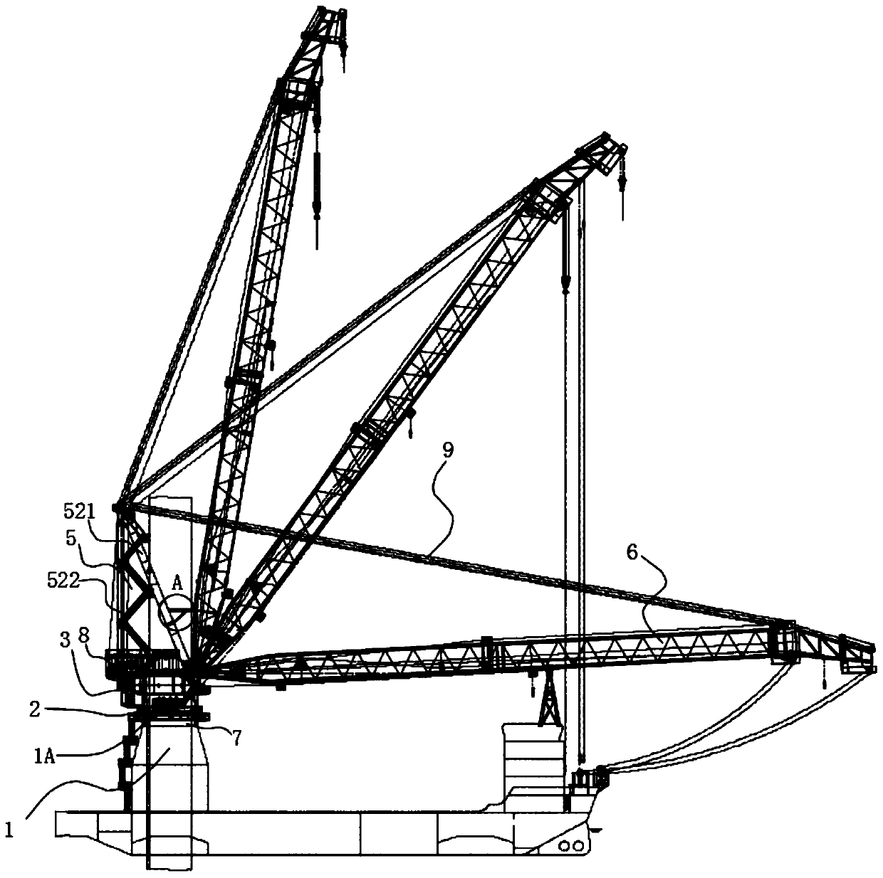
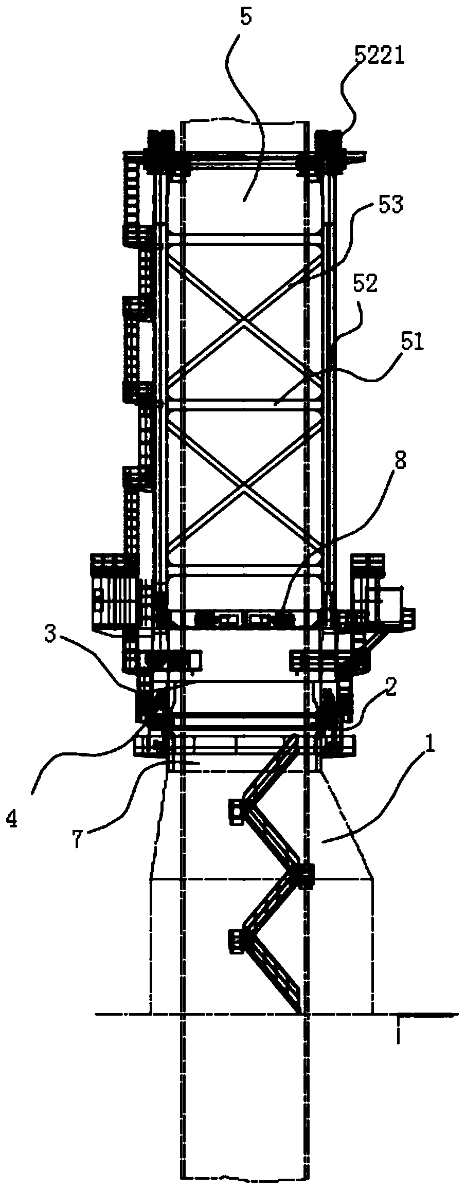
[0061] Such as Figure 1 to Figure 8 As shown, the mechanical part includes a base 1 , a slewing support 2 , a slewing platform 3 , a slewing drive 4 , a tripod 5 and a double-arm boom 6 . Such as Figure 10 to Figure 15 As shown, the hydraulic system includes an oil tank 100, a slewing system 200 for driving a slewing platform, a brake system 300, a cooling system 400 for lowering oil temperature, an oil replenishment system 500 for replenishing oil, and a system for starting when a failure occurs. The hydraulic emergency system 600.

[0062] Such as Figure 1 to Figure 8 As shown, the top of the base 1 is connected with the outer ring screw of the slewing support 2, the bottom of the slewing platform 3 is connected with the inner ri...


PUM


Abstract

The invention discloses a crane based on a hydraulic system. The crane comprises a mechanical part and a hydraulic system part; and the mechanical part comprises a base, a rotary support, a rotary platform, a triangular support and a double-arm lifting arm part, the base is connected with the rotary support, the rotary platform is mounted on the rotary support, the triangular support is fixedly mounted at the top of the rotary platform, the double-arm lifting arm part is hinged to the rotary platform, and the structure is high in lifting capacity and high in pressure-bearing capacity; and thehydraulic system comprises an oil tank, a rotary system, a braking system, a cooling system, an oil supplementing system and a hydraulic emergency system. The rotary system adopts a closed-type hydraulic system, and the energy utilizing rate is high; the braking system is internally provided with a braking shuttle valve, thus the braking system and a braking oil circuit of the hydraulic emergencysystem are connected, the braking system with two-circuit input and one-circuit output is achieved, and safety performance is high; through the cooling system, a hydraulic pump set is cooled, and thepossibility of failure of the hydraulic pump set is decreased; and the hydraulic emergency system is adopted, and thus the safety of the crane is improved.

Description

technical field [0001] The invention relates to the technical field of cranes, and specifically discloses a crane based on a hydraulic system. Background technique [0002] Offshore platform cranes are mainly cranes used on offshore platforms. It is a kind of equipment for loading and unloading goods on offshore platforms and hoisting personnel to the platform. It is one of the most important production and safety equipment in offshore oil production. Due to the harsh sea environment, It has high requirements on safety, reliability, maintainability, wind resistance and corrosion resistance. At the same time, unlike general land cranes, offshore platform cranes are generally fixed on the ship platform, and the movement of the platform itself will have a strong impact on the movement of the load. During operation, the offshore crane will pitch, roll and heave with the waves. These movements will cause the load to swing, especially during the lifting process. Such movements of...

Claims


Application Information

Patent Timeline
Patent Type & Authority Patents(China)
IPC IPC(8): B66C23/61B66C23/62F15B11/16B66C23/86
CPCB66C23/605B66C23/62B66C23/86B66C2700/03F15B11/16
Inventor 梁兆环陈懿王江李新献安万平
Owner SOUTH CHINA MARINE MACHINERY
Why Eureka
Try Eureka