Optical fiber connector

An optical fiber connector and optical fiber technology, which is applied in the direction of coupling of optical waveguides, can solve problems such as the inability to provide tension, and achieve the effect of convenient operation and good market application prospects.

Inactive Publication Date: 2014-06-18
SHENZHEN HAOTONGJIA IND
View PDF4 Cites 4 Cited by
  • Summary
  • Abstract
  • Description
  • Claims
  • Application Information

AI Technical Summary

Problems solved by technology

Such a system is convenient to use, but does not provide enough pulling force

Method used


Image

  • Optical fiber connector
  • Optical fiber connector
  • Optical fiber connector

Examples


Embodiment Construction

[0032] The present invention will be described in detail below in conjunction with the accompanying drawings and specific embodiments.

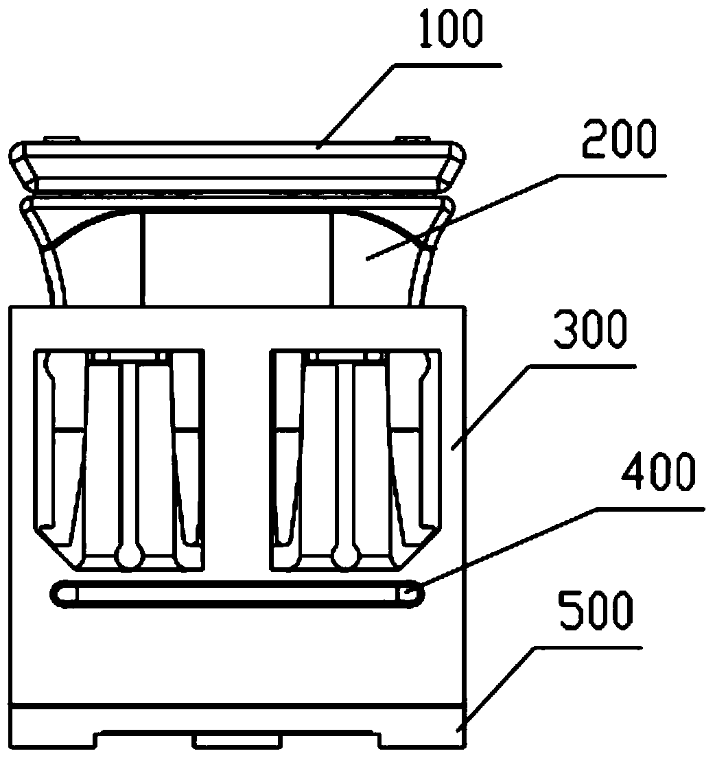
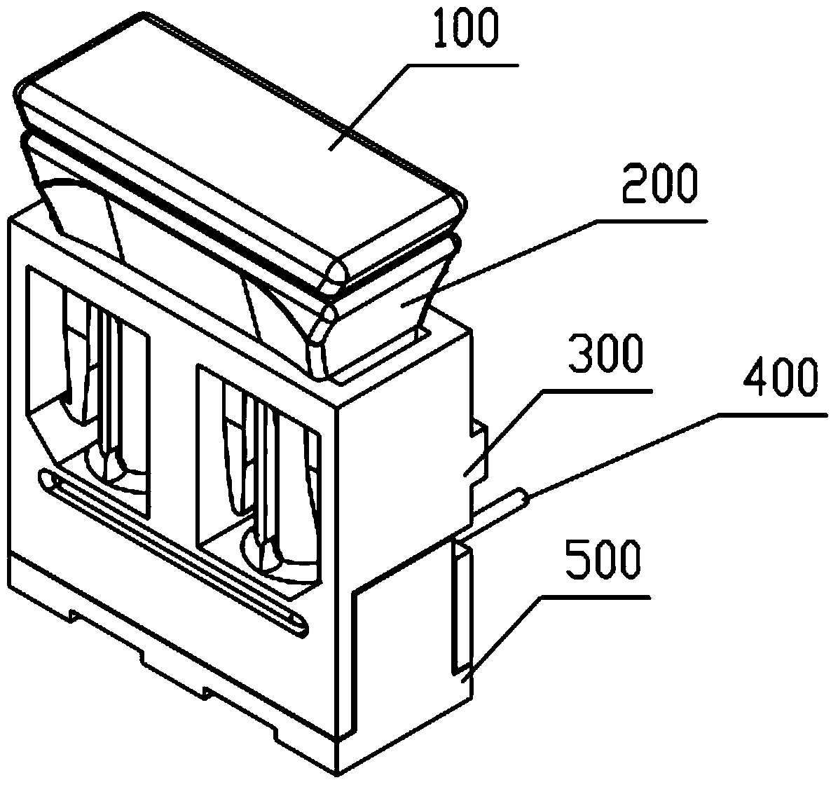
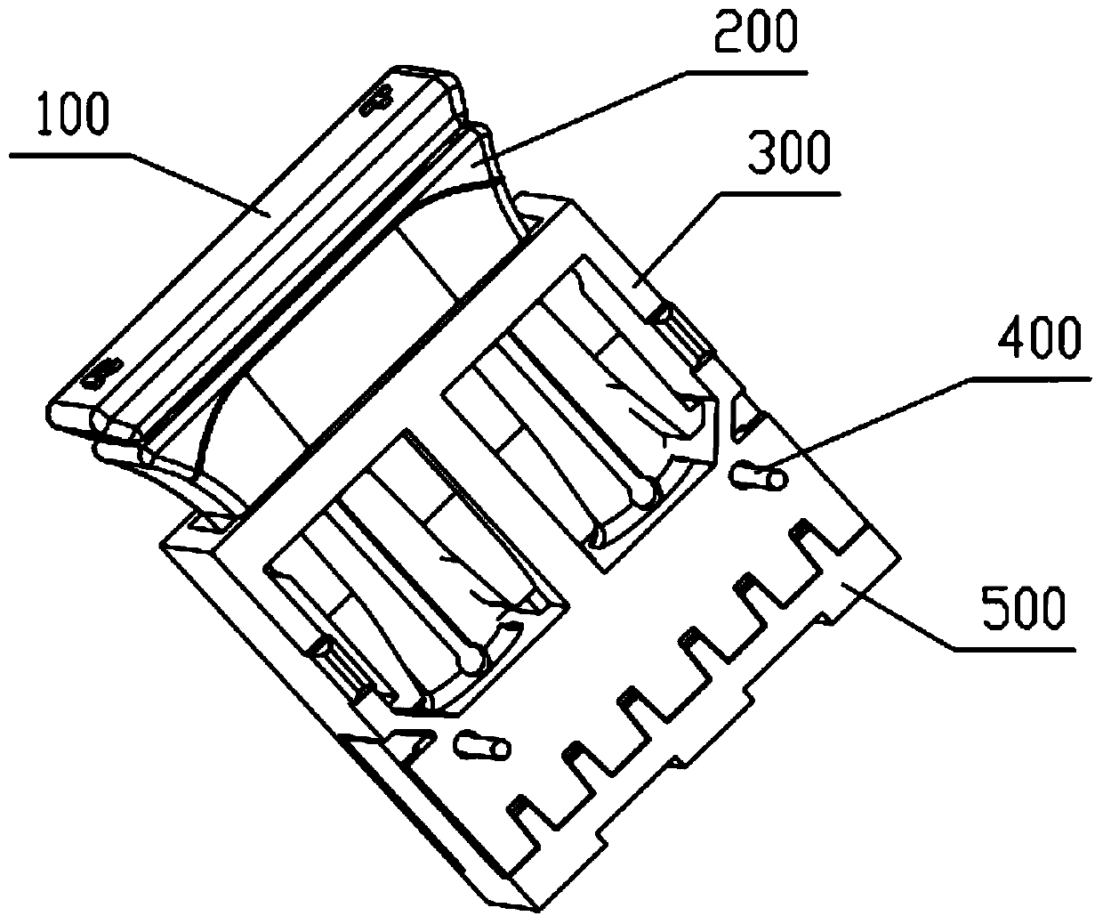
[0033] Such as figure 1 As shown, one embodiment of the present invention is an optical fiber connector, which includes: a main body 300, a clamp 200 and a rear cover 500, preferably, as figure 1 , figure 2 and image 3 As shown, the optical fiber connector also has a dust plug 100 and a fixed pin 400 . Preferably, the clamp, the main body and the rear cover are all plastic parts. Preferably, the dust plug is also a plastic part. And / or, the fixing pin is a metal part or a plastic part.

[0034] For example, another embodiment of the present invention is an optical fiber connector, which includes a clamp, a main body and a rear cover. The main body is provided with a cavity for placing an external pair of optical transceiver devices; the back cover is snapped and fixed with the main body for fixing the pair of optical transceiver devic...


PUM


Abstract

The invention discloses an optical fiber connector which comprises a clamp, a main body and a rear cover, wherein the main body is provided with a cavity which is used for containing an external optical transceiver pair; the rear cover is fixed to a buckle of the main body and is used for fixing the optical transceiver pair; the clamp is movably mounted on the main body; two guide pipes are arranged in the main body; the clamp is correspondingly provided with two mounting openings; a group of clamping sheets are arranged beside each mounting openings and comprise outer clamping parts and inner clamping parts; first ends of the outer clamping parts and the inner clamping parts are respectively and fixedly arranged on the clamp; the guide pipes are hollowly arranged and are used for penetrating through an external optical fiber; each guide pipe comprises at least two clamping parts which are arranged annularly to form the guide pipe; at least one convex part is arranged on the inner wall of each clamping part; a first end of each clamping part is fixedly arranged on the main body and is used for matching with the outer clamping parts and the inner clamping parts; when the clamping is mounted, the gaps between the outer clamping parts and the inner clamping parts are shrunk, each clamping part is clamped, the gap between adjacent clamping parts is shrunk, and optical fibers in the middle of the guide pipes are clamped by matching with each convex part.

Description

technical field [0001] The present invention relates to optical fiber connection, in particular to an optical fiber connector. Background technique [0002] At each end of the plastic optical fiber, there is usually a connector designed to mate with a connector on the device. Connectors are designed to secure and hold plastic optical fibers with connectors in the correct position in front of an electro-optic and photoelectric conversion component so that light can pass from one component to another. [0003] This method requires a connector to be installed at the end of the plastic optical fiber, and the connector has corresponding specification requirements. Generally, a special tool is required to install the connector. Inconvenient to use, especially in the case of on-site construction and installation. [0004] Alternatively, the plastic optical fiber can be directly inserted into the connector without installing a connector on the end of the plastic optical fiber. In ...

Claims


Application Information

Patent Timeline
Patent Type & Authority Applications(China)
IPC IPC(8): G02B6/42
Inventor 许杰雄
Owner SHENZHEN HAOTONGJIA IND
Why Eureka
Try Eureka