State switching method and electronic equipment
An electronic device and state switching technology, applied in the field of communication, can solve problems such as cumbersome operation flow, achieve the effect of simplifying cumbersome operations and improving user experience
- Summary
- Abstract
- Description
- Claims
- Application Information
AI Technical Summary
Problems solved by technology
Method used
Image
Examples
Embodiment 1
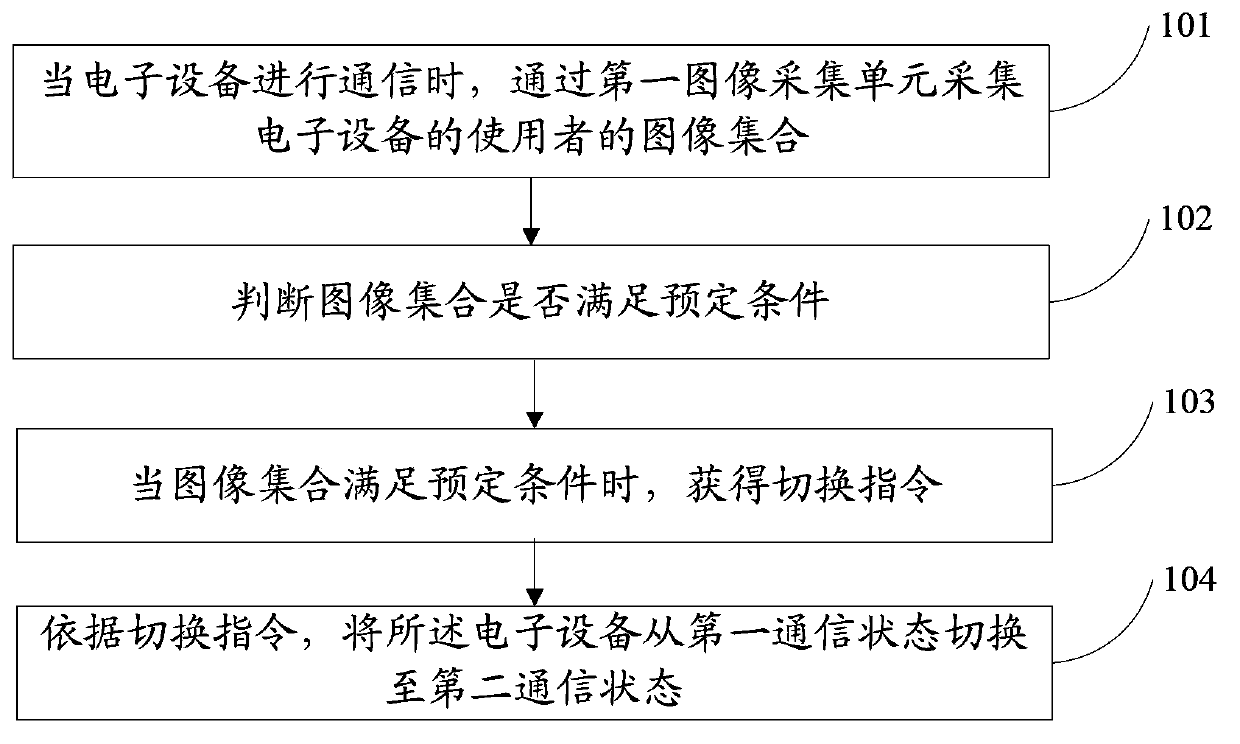
[0075] This embodiment provides a state switching method, such as figure 1 As shown, the method includes:
[0076] 101. When the electronic device communicates, use a first image acquisition unit to collect an image collection of a user of the electronic device.
[0077] Optionally, the electronic device may be a smart terminal, for example, a mobile phone, a tablet computer, and the like.
[0078] Wherein, the image set may be one image, or a series of continuous images, and the images mainly include the user's hands and mouth.
[0079] Optionally, the image collection of the user of the first electronic device may also be collected by the second image collection unit, where the image collection includes the user's eyes and / or face.
[0080] It should be noted that both the first collection unit and the second collection unit can control the camera of the terminal to collect images, and the two can control the camera independently or jointly control the camera.
[0081] 10...
Embodiment 2
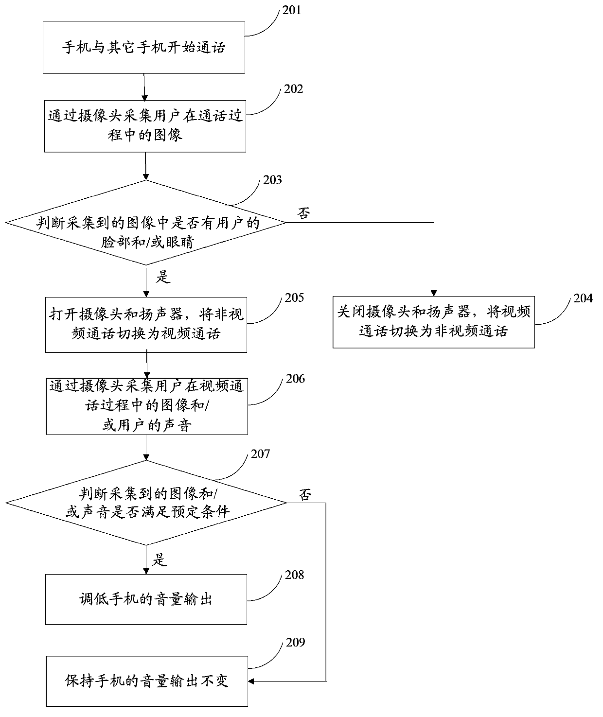
[0100] This embodiment provides a state switching method, which is applied to communication between electronic devices, taking a mobile phone as an example, such as figure 2 As shown, the method includes:
[0101] 201. The mobile phone starts talking with other mobile phones.
[0102] For example, the call may be a video call or a non-video call.
[0103] Optionally, after starting the video call, the camera is automatically turned on to provide video images to the other party through the Internet or 3G network.
[0104] Among them, in the non-video call state, only voice interaction is required between the mobile phone and other mobile phones; in the video call state, in addition to voice interaction between the mobile phone and other mobile phones, the mobile phone needs to send the collected user images to other mobile phones, and receive images of other users sent by other mobile phones, and display the images.
[0105] 202. Collect images of the user during the call t...
Embodiment 3
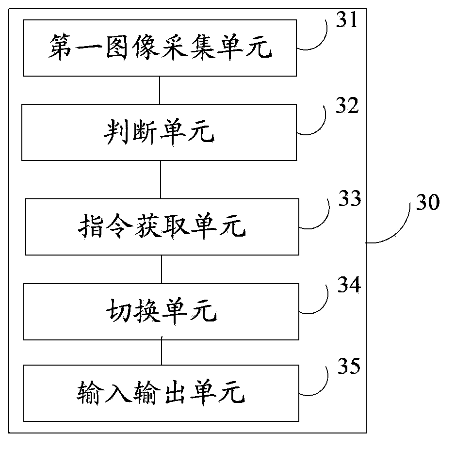
[0127] This embodiment provides an electronic device 30, such as image 3 As shown, the electronic device 30 includes:
[0128] The first image collection unit 31 is configured to collect an image collection of the user of the electronic device 30 when the electronic device 30 communicates with the second electronic device;
[0129] A judging unit 32, configured to judge whether the image collection collected by the first image collection unit 31 satisfies a predetermined condition;
[0130] An instruction acquisition unit 33, configured to obtain a switching instruction when the judging unit 32 judges that the image set satisfies the predetermined condition;
[0131] A switching unit 34, configured to switch the electronic device 30 from the first communication state to the second communication state according to the switching instruction obtained by the instruction acquiring unit 33;
[0132] The electronic device 30 also includes:
[0133] The input and output unit 35 is...
PUM
 Abstract
Description
Claims
Application Information
 - R&D
- Intellectual Property
- Life Sciences
- Materials
- Tech Scout
- Unparalleled Data Quality
- Higher Quality Content
- 60% Fewer Hallucinations
Browse by: Latest US Patents, China's latest patents, Technical Efficacy Thesaurus, Application Domain, Technology Topic, Popular Technical Reports.
© 2025 PatSnap. All rights reserved.Legal|Privacy policy|Modern Slavery Act Transparency Statement|Sitemap|About US| Contact US: help@patsnap.com


