Noise floor suppression method and device for remote coverage system

A suppression device and remote unit technology, which is applied in power management, wireless communication, electrical components, etc., can solve the problem of increasing the uplink output noise floor of the remote relay end and the downlink output noise floor of the remote radio unit, which is easy to introduce noise, Increased input noise and other issues to reduce the impact of receiving sensitivity, facilitate popularization and application, and achieve simple effects

Inactive Publication Date: 2014-06-18
COMBA TELECOM SYST CHINA LTD
View PDF6 Cites 8 Cited by
  • Summary
  • Abstract
  • Description
  • Claims
  • Application Information

AI Technical Summary

Problems solved by technology

Similarly, the input noise of the mobile terminal will also be affected by the downlink output noise floor of the remote coverage system. When the downlink output noise floor of the remote coverage system increases, the input noise of the mobile terminal will also increase, thereby reducing the receiving sensitivity of the mobile terminal.
The noise introduced by the downlink input terminal of the remote coverage system is amplified by the remote coverage system and transmitted to the downlink output terminal of the remote coverage system, making the downlink output noise floor larger
Moreover, the greater t

Method used


Image

  • Noise floor suppression method and device for remote coverage system
  • Noise floor suppression method and device for remote coverage system

Examples


Embodiment Construction

[0014] In order to further illustrate the technical means adopted by the present invention and the achieved effects, the technical solutions of the present invention will be clearly and completely described below in conjunction with the accompanying drawings and preferred embodiments.

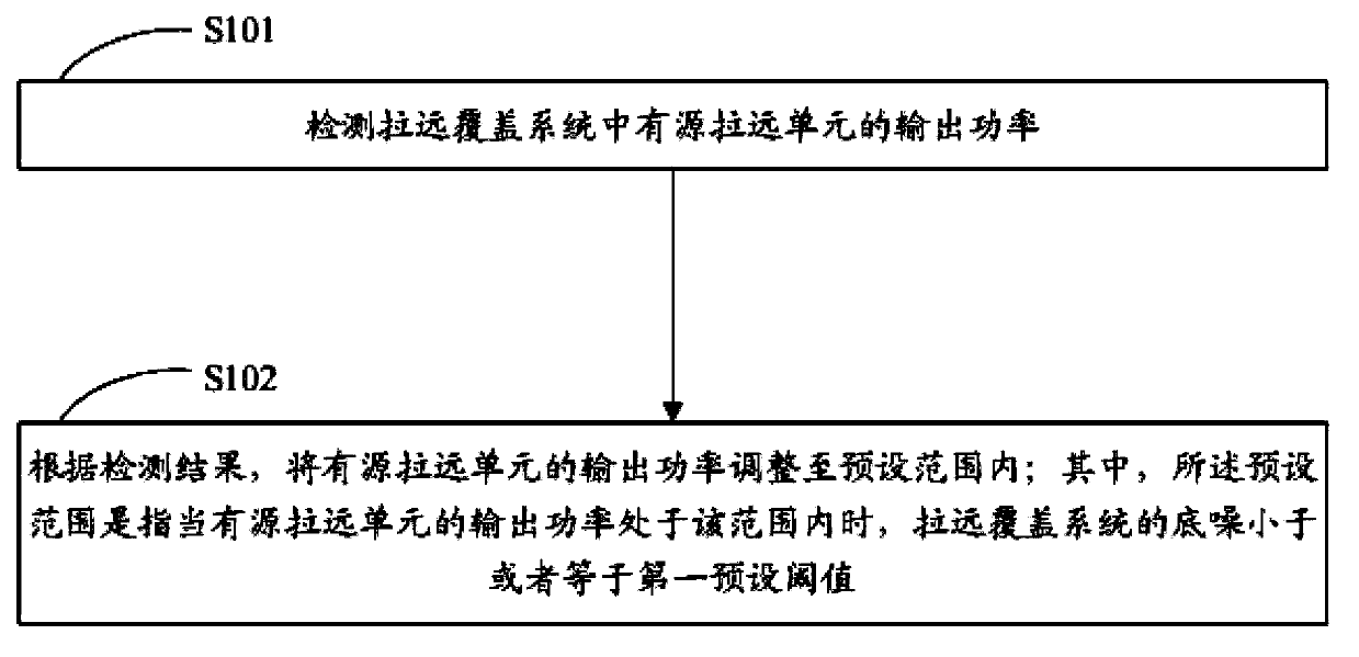
[0015] see figure 1 , is a schematic flowchart of the noise floor suppression method for the remote coverage system of the present invention. The noise floor suppression method of the remote coverage system of the present invention comprises the following steps:

[0016] S101 detects the output power of the active remote unit in the remote coverage system;

[0017] The output power of the active remote unit may include uplink output power and / or downlink output power.

[0018] Preferably, when the remote coverage system is working, the uplink output power value of the active remote unit can be detected in real time through the remote relay terminal in the remote coverage system, and the activ...


PUM


Abstract

The invention discloses a noise floor suppression method for a remote coverage system. The noise floor suppression method comprises the following steps of detecting the output power of an active remote unit in the remote coverage system; according to a detection result, adjusting the output power of the active remote unit within a preset range. The invention also discloses a noise floor suppression device for the remote coverage system. The noise floor suppression device comprises an output power detection module and an output power adjustment module. The noise floor suppression method and the noise floor suppression device for the remote coverage system can be used for automatically suppressing noise floor of the remote coverage system. By presetting a control range for the output power of the active remote unit, the output power of the active remote unit is adjusted in real time; therefore the output noise floor of the remote coverage system is controlled in a reasonable range, and the influence on the receiving sensitivity of a base station and a mobile terminal is reduced. The noise floor suppression method and the noise floor suppression device for the remote coverage system are easy to implement, convenient to use, low in cost and convenient to promote and apply.

Description

technical field [0001] The invention relates to the technical field of noise suppression, in particular to a noise suppression method for a remote coverage system and a noise suppression device for a remote coverage system. Background technique [0002] After the remote coverage system is introduced into the wireless coverage access system, the input noise of the base station will be affected by the uplink output noise floor of the remote coverage system. When the uplink output noise floor of the remote coverage system increases, the input noise of the base station will increase accordingly, thereby reducing the receiving sensitivity of the base station. The noise introduced by the uplink input terminal of the remote coverage system is amplified by the remote coverage system and transmitted to the uplink output terminal of the remote coverage system, making the uplink output noise floor larger. The greater the uplink gain of the remote coverage system, the greater the impac...

Claims


Application Information

Patent Timeline
IPC IPC(8): H04W52/18
Inventor 林福强罗漫江樊奇彦罗新军
Owner COMBA TELECOM SYST CHINA LTD
Why Eureka
Try Eureka