Check patentability & draft patents in minutes with Patsnap Eureka AI!

A special printing nozzle for printed electronics

A technology for printing nozzles and printing electronics, which can be used in printing and other directions to solve problems such as designing nozzles

Active Publication Date: 2016-05-25
HUBEI HENGDA PACKING CO LTD
View PDF8 Cites 0 Cited by
  • Summary
  • Abstract
  • Description
  • Claims
  • Application Information

AI Technical Summary

Problems solved by technology

Existing nozzles cannot meet the above requirements of printed electronics, and there is no nozzle specially designed for printed electronics on the market

Method used


Image

  • A special printing nozzle for printed electronics
  • A special printing nozzle for printed electronics
  • A special printing nozzle for printed electronics

Examples


Embodiment Construction

[0027] The present invention will be further elaborated below in conjunction with the accompanying drawings.

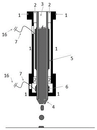
[0028] as attached figure 2 As shown, a special printing nozzle for printed electronics includes a nozzle 3 and a protective case 1, the nozzle 3 and the protective case 1 are fixed by a support part 2, the nozzle 4 and the nozzle 3 are integrated; it also includes a main The piezoelectric ceramic ring 5 and the correction voltage ceramic ring 6 surround the nozzle, and both the main piezoelectric ceramic ring 5 and the correction piezoelectric ceramic ring 6 are connected to an external power supply 16 through a wire 7 .

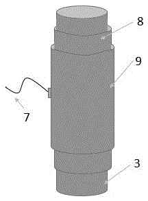
[0029] as attached image 3 As shown, the main piezoelectric ceramic ring 5 and the correction piezoelectric ceramic ring 6 are composed of a connecting part 8 and a piezoelectric ceramic 9 .

[0030] as attached Figure 4 As shown, the piezoelectric ceramic 9 is formed by bonding the substrate (silicon 10 and silicon dioxide 11), the anti-stri...


PUM

PropertyMeasurementUnit
diameteraaaaaaaaaa

Abstract

The invention discloses a printing spraying head special for printing electronics. The printing spraying head comprises a spraying pipe and a protective shell. The spraying pipe and the protective shell are fixed through a supporting portion. A spraying nozzle and the spraying pipe are integrated. A main piezoelectric ceramic ring and a correction piezoelectric ceramic ring are installed on the spraying pipe. An upper electrode of piezoelectric ceramic is connected with a wire. The wire is connected with an external power source. A voltage with a proper wave shape is input to the piezoelectric ceramic rings. It is ensured that the piezoelectric ceramic rings have an inverse piezoelectric effect and deform under the action of an electric field, and ink droplets are driven to be sprayed. According to the printing spraying head special for the printing electronics, the piezoelectric ceramic rings are adopted to replace a sheet structure in a traditional piezoelectric type spraying head, and the small piezoelectric ceramic ring is added below the spraying pipe to correct an ink spraying model, so that ink flows like laminar flow, and the requirements of the printing electronics for good chemical stability, sensitive reaction and the like of the spraying head are met.

Description

technical field [0001] The invention belongs to the field of printed electronics, and in particular relates to a special printing nozzle for printed electronics. Background technique [0002] As a sunrise industry in the global industrial manufacturing industry, printed electronics has broad application fields and good market prospects. [0003] Printed electronics (PE, PrintedElectronics) is a process and technology that uses printing to realize the manufacture of electronic circuits or electronic devices. Since the emergence of printed electronics, it has attracted the attention of all parties and triggered a research boom because of its features such as printability, wide application range, low price and high performance. According to authoritative statistics, the printed electronics application market is expected to reach US$5.2 billion in 2015. [0004] As a key component of printed microelectronics, the material printing head is one of the important factors affecting...

Claims


Application Information

Patent Timeline
Patent Type & Authority Patents(China)
IPC IPC(8): B41J2/14
Inventor 钱俊张文菡胡继承
Owner HUBEI HENGDA PACKING CO LTD
Features
  • R&D
  • Intellectual Property
  • Life Sciences
  • Materials
  • Tech Scout
  • Unparalleled Data Quality
  • Higher Quality Content
  • 60% Fewer Hallucinations
Learn More