
Temperature control ceiling fan

A ceiling fan and temperature controller technology, applied in the field of ceiling fans, can solve problems such as single function, and achieve the effect of satisfying heat dissipation

Inactive Publication Date: 2014-06-25
SHANGHAI HANGTOU SCHOOL
View PDF0 Cites 2 Cited by
  • Summary
  • Abstract
  • Description
  • Claims
  • Application Information

AI Technical Summary

Problems solved by technology

[0003] Aiming at the shortcoming that the current common ceiling fan has a single function and cannot meet the needs of all people, the present invention provides a temperature-controlled ceiling fan that can meet the public's heat dissipation and cooling requirements.

Method used


Image

  • Temperature control ceiling fan

Examples


Embodiment Construction

[0011] The present invention will be further described below in conjunction with the accompanying drawings and specific embodiments, but not as a limitation of the present invention.

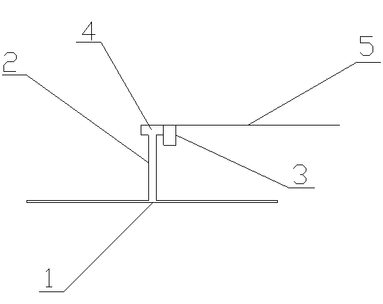
[0012] Such as figure 1 Shown is a temperature-controlled ceiling fan of the present invention, including a blade 1, a boom 2, a controller 3, a motor 4, and a power cord 5; the blade 1 is connected to the bottom of the boom 2, the motor 4 is connected to the top of the boom 2, and the controller 3 It is connected with the motor 4, and the power line 5 is connected with the controller 3.

[0013] The working principle of the above-mentioned invention is: when the temperature exceeds the set temperature of the controller 3, the controller 3 turns on and sends the electric current to the motor 4 to make the boom 2 and the blade 1 rotate; when the temperature is lower than the set temperature of the controller 3 , the controller 3 closes and stops sending current to the motor 4, and the boom 2 a...


PUM


Abstract

The invention discloses a temperature control ceiling fan comprising blades, a hanging rod, a controller, a motor and a power line. The blades are connected with the bottom of the hanging rod, the motor is connected with the top of the hanging rod, the controller is connected with the motor, and the power line is connected with the controller. The temperature control ceiling fan has the advantages that indoor apparent temperature can be maintained at an appropriate level, so that the requirement of people for relieving summer heat is met, and people cannot catch cold due to overlong time of rotation of the ceiling fan.

Description

technical field [0001] The invention relates to a ceiling fan, in particular to a temperature-controlled ceiling fan. Background technique [0002] In public places, some people have to turn on the ceiling fan even if it is not hot, causing some people to catch a cold, while the ordinary ceiling fan has only one switch and one speed regulating device, so it is difficult to satisfy different people in public places at the same time. Require. Contents of the invention [0003] Aiming at the shortcoming that the current common ceiling fan has single function and cannot meet the needs of all people, the present invention provides a temperature-controlled ceiling fan that can meet the public's requirements for relieving summer heat and cooling down. [0004] A temperature-controlled ceiling fan, including a blade, a boom, a controller, a motor, and a power cord; the blade is connected to the bottom of the boom, the motor is connected to the top of the boom, and the controller ...

Claims


Application Information

Patent Timeline
Patent Type & Authority Applications(China)
IPC IPC(8): F04D25/08F04D27/00F04D29/02
Inventor 陆洁霞
Owner SHANGHAI HANGTOU SCHOOL
Learn More