A Mesh Division Method for Finite Element Model of Turbine Blade Thermal Barrier Coating

A technology of mesh division and thermal barrier coating, which is applied in special data processing applications, instruments, electrical digital data processing, etc. problems, to achieve the effect of convenient data extraction and analysis, avoiding software compatibility problems, and simple and feasible methods

Active Publication Date: 2017-02-15
XIANGTAN UNIV
View PDF2 Cites 0 Cited by
  • Summary
  • Abstract
  • Description
  • Claims
  • Application Information

AI Technical Summary

Problems solved by technology

[0004] The mesh division of complex geometric models has always been one of the most troublesome problems for finite element modelers. There are generally two traditional methods: method one, reduce the requirements, and use lower mesh quality (such as tetrahedral mesh or Wedge grid, etc.) to divide the grid and then perform subsequent calculations, which not only has a great impact on the calculation accuracy, but also may not be able to achieve data extraction and analysis in post-processing; method two, use professional grid division software (such as Hypermesh etc.), the mesh quality obtained by using this method can be improved, but it introduces a new problem, that is, the compatibility problem between software, especially when it comes to curved surface and microscopic size, the incompatibility between software more pronounced
In addition, for modelers, it is very difficult to learn and use several complex software at the same time
For the finite element model of the thermal barrier coating of the turbine blade, due to the existence of various irregular geometric shapes such as tenons and cooling channels, the division of the mesh is particularly difficult, and a simple, feasible and high-quality mesh division is urgently needed method, but there is no related technology report

Method used


Image

  • A Mesh Division Method for Finite Element Model of Turbine Blade Thermal Barrier Coating
  • A Mesh Division Method for Finite Element Model of Turbine Blade Thermal Barrier Coating
  • A Mesh Division Method for Finite Element Model of Turbine Blade Thermal Barrier Coating

Examples


Embodiment 1

[0051] Select the single turbine blade model that has been established as the implementation object, and use the finite element software ABAQUS to establish the finite element model, mainly to carry out its finite element simulation under thermal cycle load.

[0052] For the sake of convenience and simplification, the present invention makes the following assumptions: 1) The material of each layer of TBCs is isotropic; 2) The thickness of each layer of TBCs is uniform; 3) The ideal elastic-plastic model is adopted; 4) The creep of each layer is a time-hardening model.

[0053] Firstly, the finite element model of the turbine blade thermal barrier coating is established, and the steps are as follows:

[0054] 1. Construction of geometric model of turbine blade without cooling channel

[0055] (1) Establishment of the geometric model of the blade body

[0056] (1) The establishment of the geometric model in the early stage

[0057] In the geometric model, the thermal barrier c...

Embodiment 2

[0132] In order to simplify, the second embodiment makes the following assumptions: 1) the materials of each layer of coating, base and tenon are uniform and all isotropic; 2) the thickness of each layer of coating is uniform; 3) the tenon is simplified as a cuboid; model, and only the high temperature creep of the TBC layer is considered.

[0133] The finite element model of the thermal barrier coating of the turbine blade is established according to the following steps:

[0134] (1) The establishment of the geometric model in the early stage

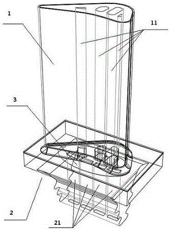
[0135] In the model, the ceramic layer is represented by TBC, and the thickness is h c ; The oxide layer is represented by TGO, the thickness is h t ; The transition layer is denoted by BC, and its thickness is h b ; The airfoil base of the turbine blade is denoted by SUB, and the thickness is h s ; The base thickness of the tenon of the turbine blade is h d , where h c =0.40mm, h t = 0.10mm, h b = 0.20mm, h s = 1.80mm, h d =...


PUM


Abstract

The invention relates to a meshing method of a finite element model of a turbine blade thermal barrier coating. The meshing is conducted in finite element software ABAQUS and comprises the following steps that the established finite element model of the turbine blade thermal barrier coating is cut into two segments of a leaf blade body and a tenon, and the cutting position is a chamfering boundary of the connecting portion of the tenon and the leaf blade body; meshing is conducted to the leaf blade body through the following steps that (1), an auxiliary line is added to connect boundary points of all layered chamfering at the same chamfering, so that a straight line perpendicular to the interface is obtained, (2), seeds are arranged, and overall seed arrangement is firstly conducted according to sizes, then rearrangement of the seeds is conducted to the auxiliary line in the thickness direction according to the number, (3), a hexahedral sweep mesh is selected and meshing is conducted to the portion; meshing is conducted to the tenon portion. The meshing method of the finite element model of the turbine blade thermal barrier coating is simple and feasible, and can be completed just by applying the finite element software ABAQUS, ensures mesh quality, and greatly improves the meshing speed.

Description

technical field [0001] The invention relates to the technical field of finite element modeling of a high-performance aeroengine turbine blade thermal barrier coating system, in particular to a grid division method for a finite element model of a turbine blade thermal barrier coating. Background technique [0002] Thermal barrier coating technology, together with cooling technology and directional solidification single crystal substrate technology, is listed as the three core technologies of the aviation propulsion plans of various countries in the world, and is a key technology that determines the development level of a country's aviation industry. Thermal barrier coating refers to the coating of high temperature resistant and high heat insulation ceramic materials on the surface of the alloy substrate to reduce the surface temperature of the substrate and improve the thermal efficiency of the engine. Facts have proved that the application of 100-400 μm thermal barrier coati...

Claims


Application Information

Patent Timeline
Patent Type & Authority Patents(China)
IPC IPC(8): G06F17/50G06F19/00
Inventor 杨丽李晓军周益春朱旺蔡灿英
Owner XIANGTAN UNIV
Why Eureka
Try Eureka