
A Radio Frequency Signal Source with the Function of Reducing Spurs

A radio frequency signal source and function technology, applied in the field of radio frequency signal sources, can solve the problems of DDS harmonics and clock harmonic spurs, and achieve the effect of optimizing the phase noise index and improving the phase detection frequency.

Active Publication Date: 2018-01-16
RIGOL
View PDF3 Cites 0 Cited by
  • Summary
  • Abstract
  • Description
  • Claims
  • Application Information

AI Technical Summary

Problems solved by technology

The existing technical solutions cannot well solve the spurious problems caused by the existence of DDS harmonics and clock harmonics

Method used


Image

  • A Radio Frequency Signal Source with the Function of Reducing Spurs
  • A Radio Frequency Signal Source with the Function of Reducing Spurs
  • A Radio Frequency Signal Source with the Function of Reducing Spurs

Examples


Embodiment Construction

[0022] In order to make the purpose, technical solutions and advantages of the embodiments of the present invention clearer, the technical solutions in the embodiments of the present invention will be clearly and completely described below in conjunction with the drawings in the embodiments of the present invention. Obviously, the described embodiments It is a part of embodiments of the present invention, but not all embodiments. Based on the embodiments of the present invention, all other embodiments obtained by persons of ordinary skill in the art without making creative efforts belong to the protection scope of the present invention.

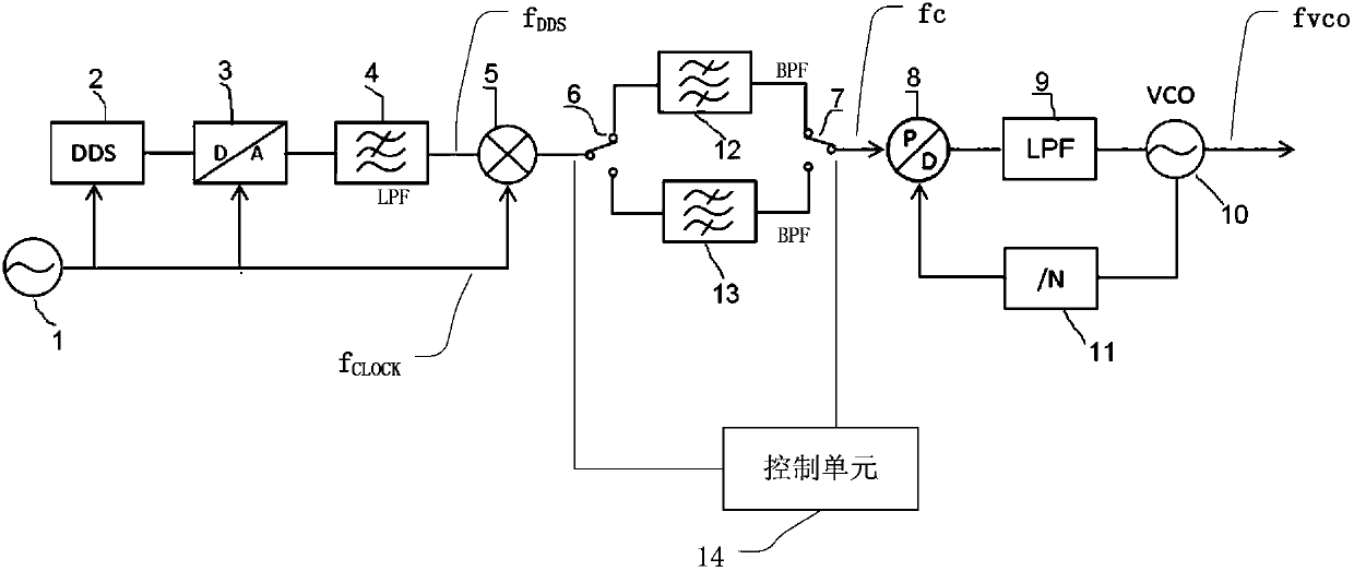
[0023] The embodiment of the present invention provides a radio frequency signal source, and the technical solution of the embodiment of the present invention may also be applied to the design of a phase-locked loop of a local oscillator system in a spectrum analyzer.

[0024] The scheme of the embodiment of the present invention utilizes the...


PUM


Abstract

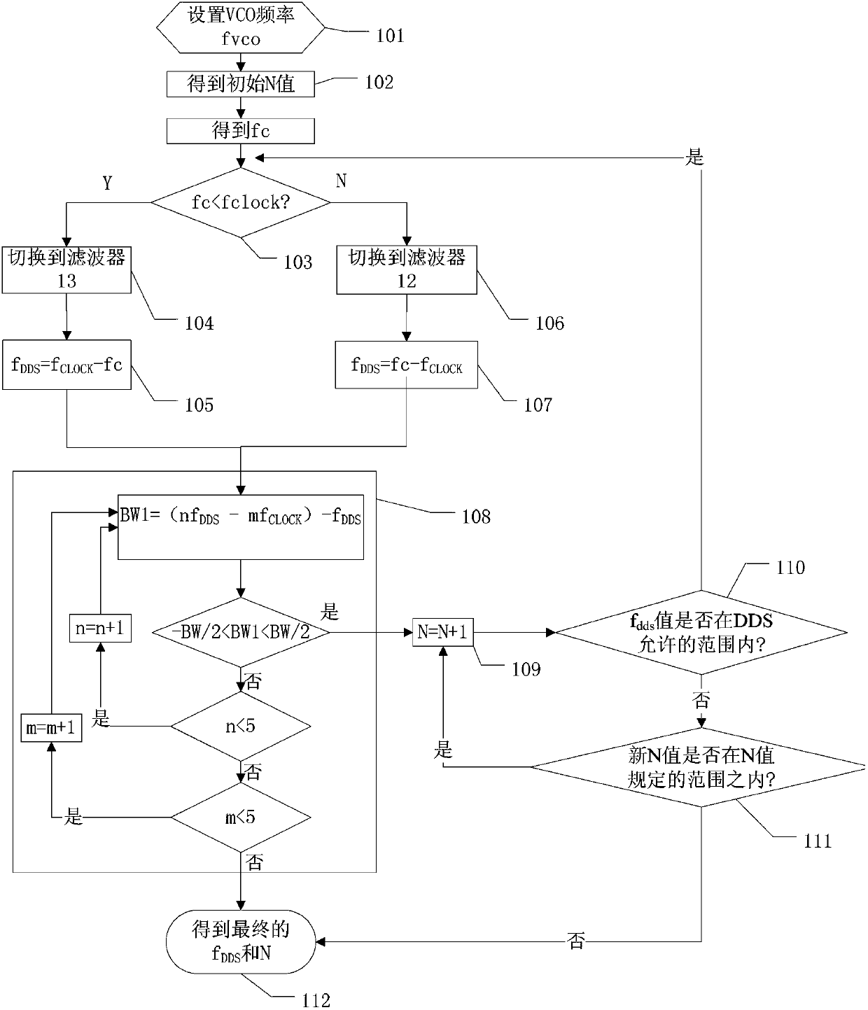
The invention provides a radio frequency signal source with the function of reducing spurs, including a reference clock, a direct digital frequency synthesizer DDS, a mixer and a phase-locked loop, and the phase-locked loop includes a phase detector, a voltage-controlled oscillator and a frequency divider ; The clock frequency of the reference clock is fCLOCK, and the output frequency of DDS is fDDS; the first bandpass filter, with a passband from fCLOCK to fDDS+fCLOCK, is connected between the mixer and the phase detector; the second bandpass filter , the passband is fCLOCK‑fDDS to fCLOCK, connected between the mixer and the phase detector; the switch unit is set at at least one end of the first and second bandpass filters; the control unit, when fDDS and fCLOCK are in the frequency mixing When adding at the mixer, switch the switch unit to only gate the first band-pass filter; when fCLOCK and fDDS are subtracted at the mixer, switch the switch unit to gate only the second band-pass filter. This signal source reduces spurs caused by mixing DDS harmonics with clock harmonics.

Description

technical field [0001] The invention relates to the field of measurement and testing, in particular to a radio frequency signal source with the function of reducing stray. Background technique [0002] DDS is the abbreviation of Direct Digital Frequency Synthesizer. Its working process is to first generate a series of discrete digital signals, and then convert them into continuous analog signals through DAC. Such as figure 1 The DDS principle block diagram of the prior art shown, when the DDS works, the frequency control word is first given by the microcontroller to the phase accumulator, and then the phase accumulator is accumulated once in each clock cycle, and the phase value obtained is in each cycle. The clock is sent to the sinusoidal lookup table in binary form, and the lookup table sends the corresponding phase amplitude signal to the DAC. The DAC continuously receives the discrete sinusoidal waveform information and converts it into an analog signal, and passes thr...

Claims


Application Information

Patent Timeline
Patent Type & Authority Patents(China)
IPC IPC(8): H03L7/18
Inventor 何毅军王悦王铁军李维森
Owner RIGOL
Learn More