
a magnetic hinge

A magnetic force and hinge technology, applied in the field of hardware parts, can solve problems such as no lubricating structure, hinge damage, affecting the hinge effect, etc., and achieve the effect of long service life

Active Publication Date: 2016-03-23
SUZHOU SAISHUOLA STAINLESS STEEL PROD CO LTD
View PDF6 Cites 2 Cited by
  • Summary
  • Abstract
  • Description
  • Claims
  • Application Information

AI Technical Summary

Problems solved by technology

Moreover, the traditional hinge structure usually does not have a lubricating structure, so the hinge often wears or rusts after being used for a period of time, affecting the hinge effect, or directly causing damage to the hinge

Method used


Image

  • a magnetic hinge
  • a magnetic hinge
  • a magnetic hinge

Examples


Embodiment Construction

[0011] Below in conjunction with embodiment the present invention is further described:

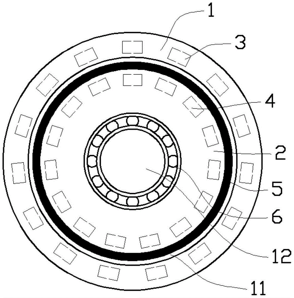
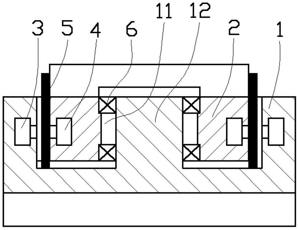
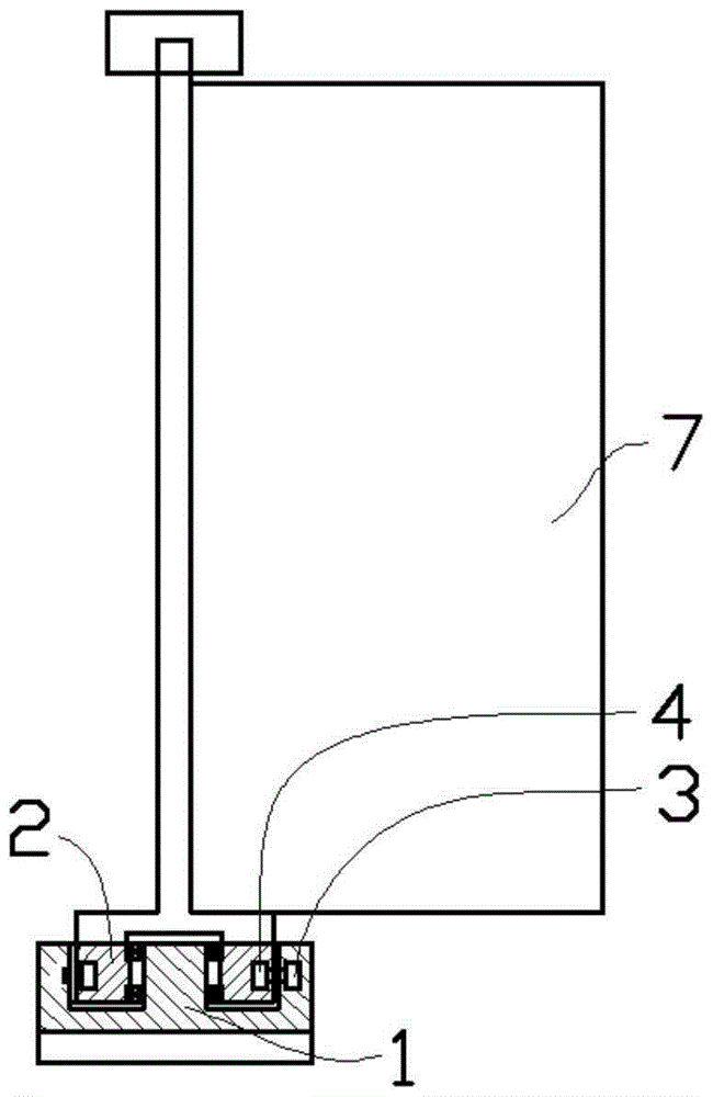
[0012] Such as figure 1 and figure 2 As shown in the embodiment, the magnetic hinge includes a fixed base 1 and a rotating base 2; the fixed base 1 is in the shape of a flat cylinder, and an annular groove 11 is designed on its upper surface, and the rotating base 2 is in the shape of a ring; On the outer wall of the fixed base 1 close to the annular groove 11, there are evenly distributed outer magnetic blocks 3 whose magnetic force points to the axial direction of the annular groove 11, and the inner part of the rotating seat 2 is equipped with a magnetic force facing the outer magnetic block at a position close to the outer wall. The inner magnetic block 4 of 3, the opposite surface of the outer magnetic block 3 and the inner magnetic block 4 adopt opposite magnetic poles;

[0013] This magnetic hinge is used to hinge the door parts, and its specific assembly method is as follows: ...


PUM


Abstract

The invention provides a magnetic hinge which comprises a fixed base and a rotary seat. An annular groove is formed in the upper surface of the fixed base. Outer magnetic blocks are evenly distributed at the positions, close to the outer wall of the annular groove, in the fixed base. The magnetic force of each outer magnetic block points to the axis of the annular groove. Inner magnetic blocks are assembled to the positions, close to the outer wall, inside the rotary seat. The magnetic force of each inner magnetic block directly faces the corresponding outer magnetic block. The magnetic poles of the opposite sides of each outer magnetic block and the corresponding inner magnetic block are opposite. The rotary seat is rotatably assembled to a cylindrical boss in the middle of the fixed seat. The magnetic hinge has the advantages that automatic closing a door leaf under small force can be prevented, magnetic abrasion can be prevented by using the magnetic force as resistance, and the service life of the magnetic hinge is prolonged.

Description

technical field [0001] The invention relates to the technical field of hardware parts, in particular to a magnetic hinge. Background technique [0002] Doors or windows are often connected by hinges (also known as hinges). The hinges can make the doors, windows and walls of the wall cabinets hinged to facilitate horizontal or vertical opening. When the hinge structure is opened and rotated horizontally along the vertical axis, although it can rotate freely in the axial direction, it is very easy to automatically close the doors and windows when encountering some external force or wind blowing, thereby shutting people out or harming people. cause bumps. At the same time, the hinges we usually use on the door are to hang the door to the door frame, so that the door will inevitably have some deformation and drooping after a long period of opening and closing. Moreover, the traditional hinge structure usually does not have a lubricating structure, so the hinge often wears or r...

Claims


Application Information

Patent Timeline
Patent Type & Authority Patents(China)
IPC IPC(8): E05D1/00E05D11/02
Inventor 钱小伟
Owner SUZHOU SAISHUOLA STAINLESS STEEL PROD CO LTD
Learn More