Clearance measurement device and method for bearing holding in shaft holding box of locomotive

A technology of measuring device and axle box body, which is used in mechanical clearance measurement, mechanical bearing testing, etc., can solve the problem of the deviation between the bearing clearance value and the actual value, and achieve the effect of accurate measurement results.

Active Publication Date: 2014-07-09
CRRC LUOYANG CO LTD
View PDF7 Cites 0 Cited by
  • Summary
  • Abstract
  • Description
  • Claims
  • Application Information

AI Technical Summary

Problems solved by technology

[0002] The existing method of measuring the clearance of the bearing is mainly to use a crowbar to act on the suspension rod of the motor of the shaft holding box to generate a component force in the direction of the Z axis to move the shaft holding box upwards, and the moving distance is passed through the magnetic seat type dial indicator The display shows that the reading is the actual clearance value of the bearing, but at the same time, a component force in the negative direction of the X axis is generated. Since the shaft holding box is a semi-shaft holding box, this component force will cause the center line of the bearing cavity at both ends of the shaft holding box to no longer Overlapping, the shaft holding box will produce a certain elastic deformation, and the measured clearance value of the holding bearing with this process method will deviate from the actual value

Method used


Image

  • Clearance measurement device and method for bearing holding in shaft holding box of locomotive
  • Clearance measurement device and method for bearing holding in shaft holding box of locomotive

Examples


Embodiment Construction

[0015] The present invention is described in conjunction with accompanying drawing and specific embodiment:

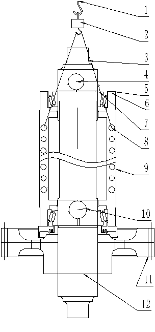
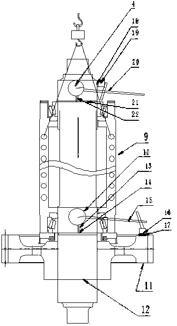
[0016] After the shaft-holding box is assembled, if figure 1 , use the hook of the crane to lift the electronic scale 2 equipped with the sling 3, and install the sling 3 on the two bolt holes 8 above the shaft holding box 9 to ensure that the shaft holding box is balanced during lifting. The hook of the car is directly above the axle 12, wipe the upper surface of the driven gear ring gear 17 clean with a lint-free towel, put the magnetic seat II16 of the magnetic seat dial indicator II10 on the driven gear ring gear 17, and adjust the The support rod II15 of the seat dial indicator II makes the measuring rod II14 of the magnetic seat dial indicator II10 vertically press against the gear end sub-box surface 14 of the shaft holding box body (the processing surface perpendicular to the shaft holding box motor mounting seat) , adjust the magnetic seat dial indicator II10...


PUM


Abstract

The invention discloses a clearance measurement device and method for bearing holding in a shaft holding box of a locomotive. The shaft holding box is stably lifted through an electronic scale; when the reading value of the electronic scale is a critical value of the sum of the weight of a shaft holding box assembly, the weight of a driven gear, the weight of an axle and the weight of other parts, the axial movement distance of the shaft holding box is the bearing holding clearance. In the whole measurement process, a non-tooth end bearing does not make displacement through measurement of a dial indicator, or else the result is invalid. Because the two ends of each motor mounting bolt hole of the shaft holding box are evenly stressed, the shaft holding box will not make elastic deformation, and therefore it is guaranteed that the measurement result is accurate.

Description

technical field [0001] The invention belongs to the technical field of locomotive maintenance, and mainly relates to a device and a method for measuring clearance of a bearing in a locomotive axle housing. Background technique [0002] The existing method of measuring the clearance of the bearing is mainly to use a crowbar to act on the suspension rod of the motor of the shaft holding box to generate a component force in the direction of the Z axis to move the shaft holding box upwards, and the moving distance is passed through the magnetic seat type dial indicator The display shows that the reading is the actual clearance value of the bearing, but at the same time, a component force in the negative direction of the X axis is generated. Since the shaft holding box is a semi-shaft holding box, this component force will cause the center line of the bearing cavity at both ends of the shaft holding box to no longer Overlapping, the shaft holding box will produce a certain elasti...

Claims


Application Information

Patent Timeline
Patent Type & Authority Applications(China)
IPC IPC(8): G01B5/14G01M13/04
Inventor 肖志强魏果果白银
Owner CRRC LUOYANG CO LTD
Why Eureka
Try Eureka