Hob mounting structure for raise boring machine

A technology for installation structure and raise drilling rig, which is applied to drill bits, drilling equipment, earth-moving drilling, etc., can solve the problems affecting the operation accuracy of the hob disc, the harm of axial movement, and the high processing cost, so as to reduce the risk of loosening and fracture. , The effect of eliminating the axial assembly gap and reducing the processing cost

Pending Publication Date: 2021-04-09
HUNAN CHUANGYUAN HIGH TECH MACHINERY CO LTD
View PDF0 Cites 0 Cited by
  • Summary
  • Abstract
  • Description
  • Claims
  • Application Information

AI Technical Summary

Problems solved by technology

[0004] In the prior art, the axial positioning of the central axis of the hob is achieved through the interference fit between the shoulders at both ends and the inner end surface of the hob seat. The elastic deformation of the end of the hob causes a gap between the shoulders at both ends of the central shaft of the hob and the inner surface of the hob seat, resulting in axial movement of the central shaft of the hob, and the axial movement will cause two major hazards. One is to affect the hob The working accuracy of the cutter head, the second is that the bolts fixing the central axis of the hob will directly bear the radial bending load. Under the bending load for a long time, the bolts at both ends of the hob seat will loosen and break in the hob seat. Drill or weld the broken end of the bolt out of the hob, which is easy to damage the thread of the hob, improper operation or even cause the hob to be scrapped directly; The axial positioning is realized by positive fit, and there are usually strict machining accuracy requirements for the shoulder size of the central axis of the hob and the inner dimension of the hob seat, which makes it difficult to control the dimensional accuracy of the existing tool seat structure, and the processing cost is higher

Method used


Image

  • Hob mounting structure for raise boring machine
  • Hob mounting structure for raise boring machine
  • Hob mounting structure for raise boring machine

Examples


Embodiment

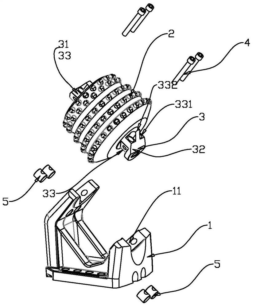
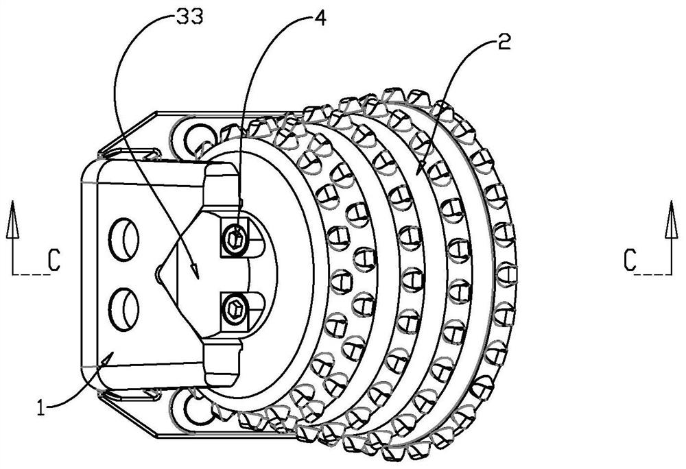
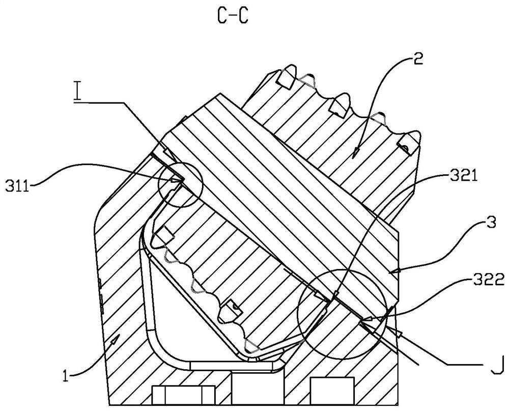
[0038] refer to Figure 1-Figure 5 , the present invention provides a hob installation structure for a patio drilling machine, comprising a hob holder 1, a hob 2 and a hob center shaft 3 for fixedly installing the hob 2, the hob center shaft 3 has a first end 31 and a second end end 32, and the first end 31 and the second end 32 are respectively provided with V-shaped parts 33, and the V-shaped parts 33 at both ends are respectively connected with the first shaft shoulder 311 and the second shaft shoulder 321 inwardly along the axial direction, and in The second end 32 is spaced apart from the second shoulder 321 and has a third shoulder 322 axially outward;

[0039]Both ends of the hob holder 1 are provided with V-shaped grooves 11 corresponding to the V-shaped portion 33, and both sides of the hob holder 1 have a first inner side wall 12 and a second inner side wall 13, and the The second inner side wall 13 is also provided with a third side wall 14 outward, and the distanc...


PUM


Abstract

The invention provides a hob mounting structure for a raise boring machine. The hob mounting structure comprises a hob holder, a hob and a hob center shaft for fixedly mounting the hob, wherein the hob center shaft is provided with a first end and a second end, the first end and the second end are provided with V-shaped parts respectively, the V-shaped parts at the two ends are sequentially connected with a first shaft shoulder and a second shaft shoulder respectively, and a third shaft shoulder is further arranged at the second end in a spaced mode through the second shaft shoulder; V-shaped grooves corresponding to the V-shaped parts are formed in the two ends of the hob holder, a first inner side wall and a second inner side wall are arranged on the two sides of the hob holder, and a third side wall is further arranged on the second inner side wall outwards; and the V-shaped parts at the two ends of the hob center shaft are fixed in the corresponding V-shaped grooves through bolts, the first shaft shoulder is in clearance connection with the first inner side wall, the second shaft shoulder is in interference connection with the second inner side wall, and the third shaft shoulder is in interference connection with the third side wall. Through the arrangement, the probability of axial movement of the hob center shaft is reduced, and therefore the risk of bolt breakage is reduced.

Description

technical field [0001] The invention relates to the technical field of mining machinery, in particular to a hob installation structure for a raise drilling machine. Background technique [0002] Raise drilling rig, as an important mining equipment, is widely used in shaft construction with lower transport roadways and stable geological conditions. It mainly uses hydraulic transmission to make the hydraulic motor obtain rotary torque, drive the drilling tool system, drive the drill pipe and The drill bit rotates, and at the same time, the propulsion cylinder applies the drill bit for propulsion when drilling, and applies the cutterhead for anti-lifting force and acts on the rock when reaming. [0003] During the reaming operation of the raise drilling rig, the hob on the cutter head performs pure rolling cutting or slight displacement along the rock working face at the bottom of the well under the double action of rotation and backlifting, resulting in an impact load. The hob...

Claims


Application Information

Patent Timeline
Patent Type & Authority Applications(China)
IPC IPC(8): E21B10/43E21B10/62E21B7/28
CPCE21B7/28E21B10/43E21B10/62
Inventor 唐安平未崴
Owner HUNAN CHUANGYUAN HIGH TECH MACHINERY CO LTD
Why Eureka
Try Eureka