Bearing set with an angular ball bearing and cylinder roller bearing receiving axial forces

A technology of cylindrical roller bearings and angular contact ball bearings, applied in the field of bearing sets, to achieve the effect of improving cost advantages

Inactive Publication Date: 2008-11-19
SCHAEFFLER TECH AG & CO KG
View PDF0 Cites 3 Cited by
  • Summary
  • Abstract
  • Description
  • Claims
  • Application Information

AI Technical Summary

Problems solved by technology

[0004] The disadvantage here is that four-point contact ball bearings only offer a contact angle of 35° as standard
In addition, four-point contact ball bearings are more expensive

Method used


Image

  • Bearing set with an angular ball bearing and cylinder roller bearing receiving axial forces

Examples


Embodiment Construction

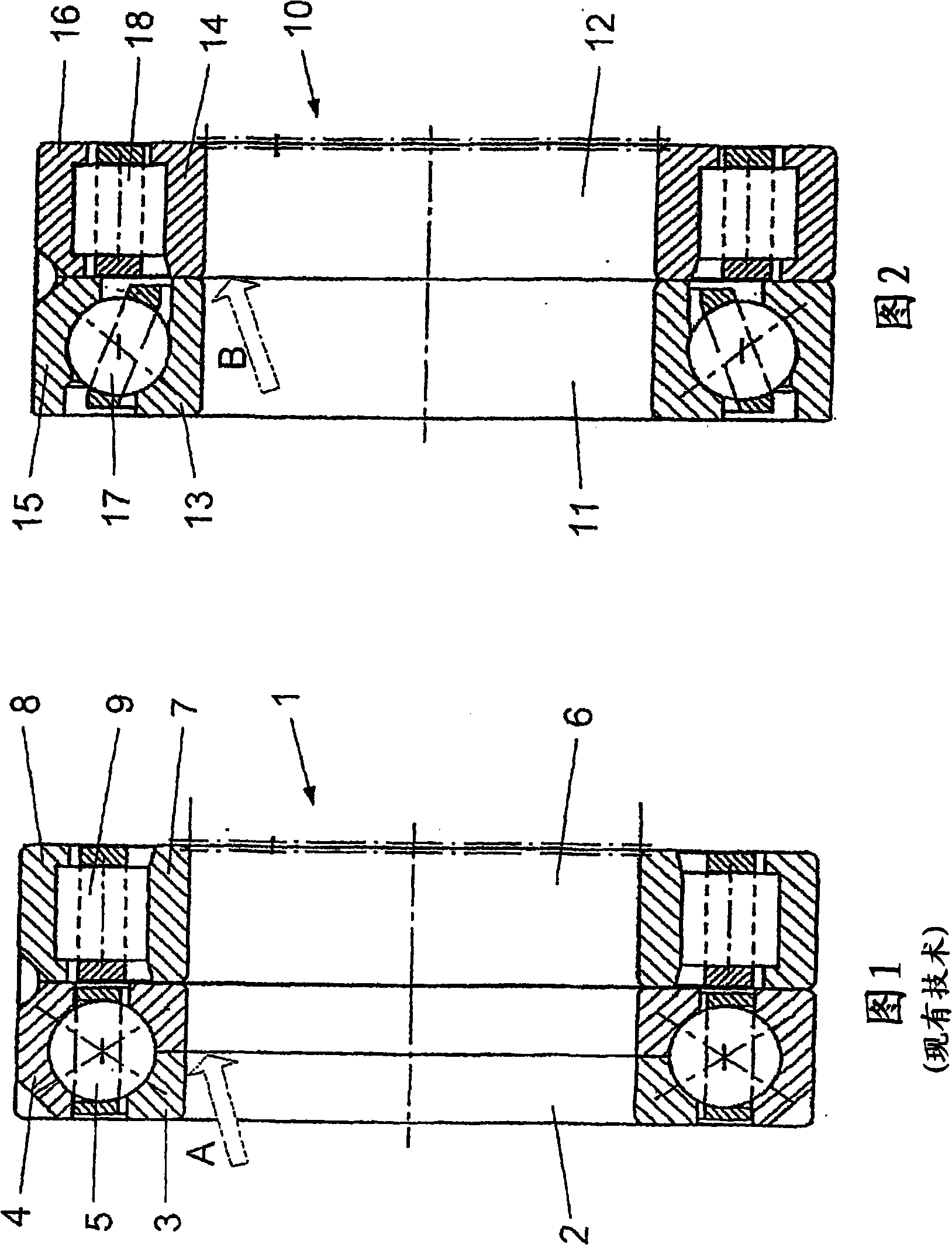
[0019] The bearing set 1 according to the prior art shown in FIG. 1 comprises a QJ bearing 2 designed as a four-point contact ball bearing and an NU axial bearing 6 designed as a bearing with a rib on the outer ring, said OJ bearing having Balls 5 between inner ring 3 and outer ring 4 , said NU axial bearing has cylindrical rollers 9 guided between inner ring 7 and outer ring 8 . Among them, the axial clearance is adjusted according to arrow A in the four-point contact ball bearing.

[0020] According to the invention, the bearing set 10 according to FIG. 2 comprises an angular contact ball bearing 11 and an NJ cylindrical roller bearing 12 designed as a thrust bearing. The two bearings 11 and 12 each have an inner ring 13 and 14 and each an outer ring 15 and 16 , between which balls 17 or cylindrical rollers 18 are accommodated.

[0021] A very small axial clearance according to arrow B is formed between the inner ring 13 of the angular contact ball bearing 11 and the inner ...


PUM


Abstract

The invention relates to a bearing set (10) for a shaft to be guided in an axially restricted and exact manner, a running wheel or the like for machine units. The aim of the invention is to devise less expensive bearings for receiving comparatively low axial back pressure forces. The bearing set (10) consists of a ball bearing (11), especially an angular ball bearing, receiving axial back pressure forces due to operation, and a ring slide bearing receiving axial back pressure forces or a cylinder roller bearing configured as a support bearing and receiving axial back pressure forces.

Description

technical field [0001] The invention relates to a bearing set for a narrowly and precisely guided shaft or the like in the axial direction, for example a rotor or other machine components. Background technique [0002] In all areas of machine construction in which impellers, such as fan wheels etc., must be axially guided very narrowly relative to the surrounding structure, especially when supporting axially very precisely guided shafts , for example on drive shafts, bearing sets consisting of various bearing types are used. [0003] Bearing sets consisting of four-point contact ball bearings (so-called QJ bearings) and radial bearings with ribs on the outer ring (so-called NU bearings) are usually used. Such a bearing combination is known, for example, from the publication WL 00 200 / 5 DA S.150 of the FAG company OEM and Trade AG. In this case, the combination is used for a combined shaft-mounted transmission and herringbone gearing. [0004] A disadvantage here is that f...

Claims


Application Information

Patent Timeline
Patent Type & Authority Applications(China)
IPC IPC(8): F16C19/54F16C19/16F16C19/26
CPCF16C19/54F16C19/163F16C19/26F16C19/541
Inventor J·格奥尔吉R·莫勒
Owner SCHAEFFLER TECH AG & CO KG
Why Eureka
Try Eureka