Ball screw driving structure for numerically-controlled machine tool

A ball screw and drive structure technology, applied in metal processing mechanical parts, metal processing equipment, feeding devices, etc., can solve the problem of not finding the ball screw drive structure of CNC machine tools, and achieve high transmission positioning accuracy and reduce shaft size. The effect of the gap

Inactive Publication Date: 2013-01-09
JIANGSU HUANYANG COMBINATION MACHINE
View PDF6 Cites 3 Cited by
  • Summary
  • Abstract
  • Description
  • Claims
  • Application Information

AI Technical Summary

Problems solved by technology

After retrieving relevant documents, no CNC machine tool ball screw driving stru

Method used


Image

  • Ball screw driving structure for numerically-controlled machine tool
  • Ball screw driving structure for numerically-controlled machine tool
  • Ball screw driving structure for numerically-controlled machine tool

Examples


Embodiment Construction

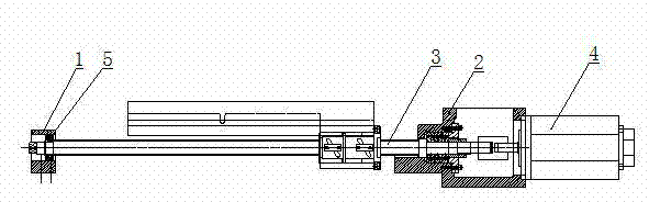
[0010] Such as figure 1 As shown, it includes a bearing seat 1, a transmission box 2, a ball screw 3 and a motor 4.

[0011] The bearing seat 1 is fixed on one end of the machine tool base, and the transmission box 2 is fixed on the other end of the machine tool base.

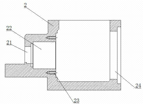
[0012] Such as figure 2 As shown, one side wall of the transmission box 2 is provided with a through hole horizontally passing through the side wall of the transmission box 2. The through hole is stepped and consists of a shaft hole 21 and a bearing hole 22 that are coaxially arranged. The inner diameter is smaller than the inner diameter of the bearing hole 22, and the bearing hole 22 is located on the inner side of the side wall, and a number of circularly distributed threaded holes 23 are drilled on the inner wall of the transmission case at the end of the bearing hole; the other side of the transmission case is provided with a motor installation 孔24.

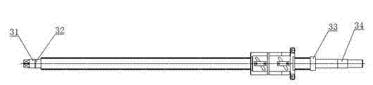
[0013] Such as image 3 As shown, the left end of the ball sc...


PUM


Abstract

The invention relates to a ball screw driving structure for a numerically-controlled machine tool. The ball screw driving structure for the numerically-controlled machine tool is innovatively characterized by comprising a bearing seat, a transmission case, a ball screw and a motor, the bearing seat is fixed at one end of a machine tool base, the transmission case is fixed at the other end of the machine tool base, the left end of the ball screw is supported in the bearing seat through a bearing pack A, the right end of the ball screw is supported in the transmission case through a bearing pack B, the motor is mounted on a motor mounting hole of the transmission case, and an output shaft of the motor is connected with the right end of the ball screw through a coupler. The ball screw driving structure for the numerically-controlled machine tool has the advantages that the ball screw driving structure is applicable to medium-speed rotating and high-precision use conditions as one end of the ball screw is fixed while the other end of the ball screw is movable; and the bearing pack B is axially limited by the aid of a pressing ring, an inner ring lock nut, an inner ring limit step of the ball screw and the transmission case step face, axial clearance is reduced beneficially, and transmission and positioning precision is high.

Description

Technical field [0001] The invention relates to a numerical control machine tool, in particular to a ball screw driving structure of the numerical control machine tool. Background technique [0002] The ball screw pair is a mechanical element composed of screw rods, nuts, balls and other parts, and its function is to change the rotary motion into linear motion. The ball screw pair has the advantages of high transmission efficiency, low wear, balanced movement, no creeping phenomenon, and high transmission accuracy. It is a further extension of the traditional sliding screw. Because of its excellent friction characteristics, the ball screw pair is widely used in various industrial equipment and precision instruments. Especially in recent years, as the linear drive execution unit of CNC machine tools, the ball screw pair has been widely used in the machine tool industry, which has greatly promoted the development of CNC machine tools. In order to obtain high transmission accuracy...

Claims


Application Information

Patent Timeline
IPC IPC(8): B23Q5/40
Inventor 朱天白
Owner JIANGSU HUANYANG COMBINATION MACHINE
Why Eureka
Try Eureka