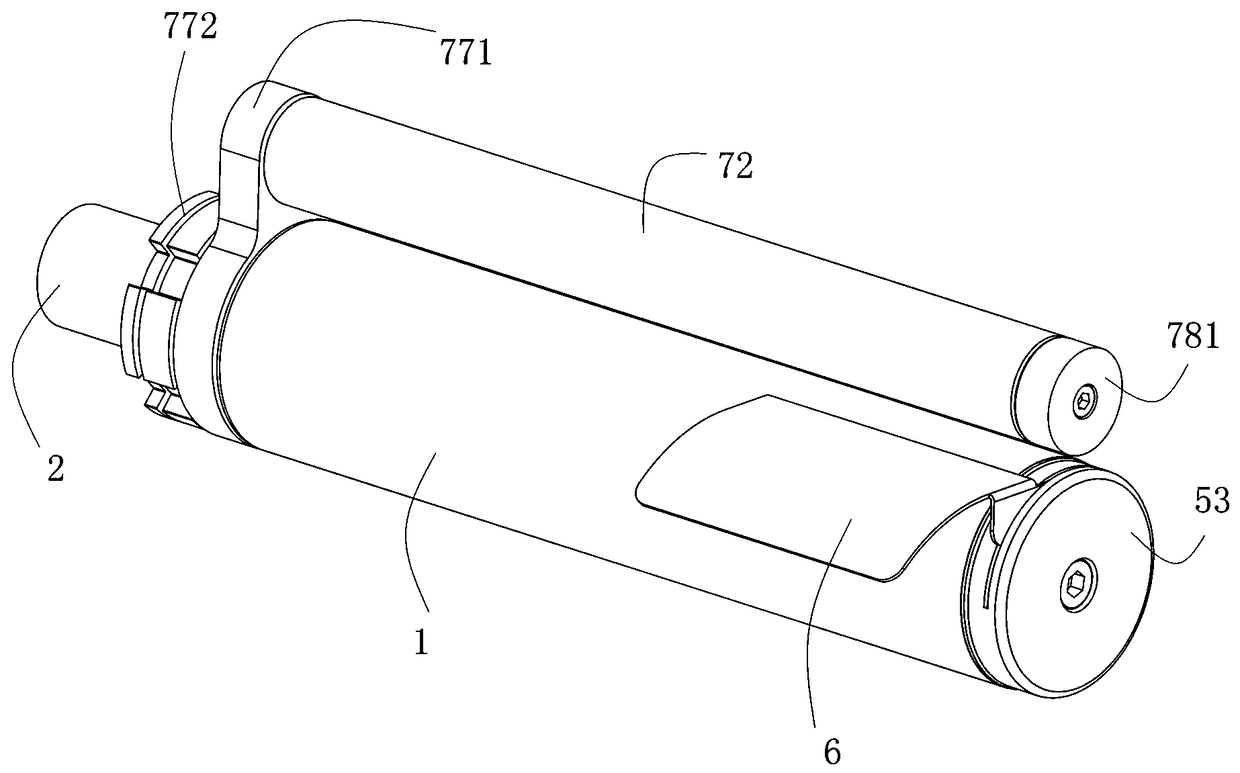
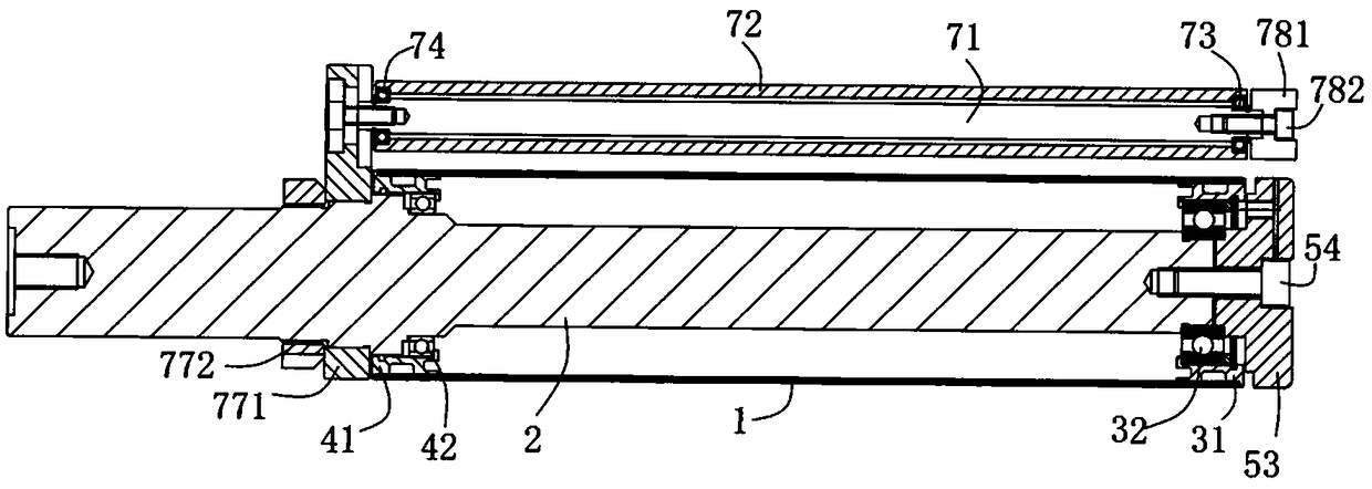
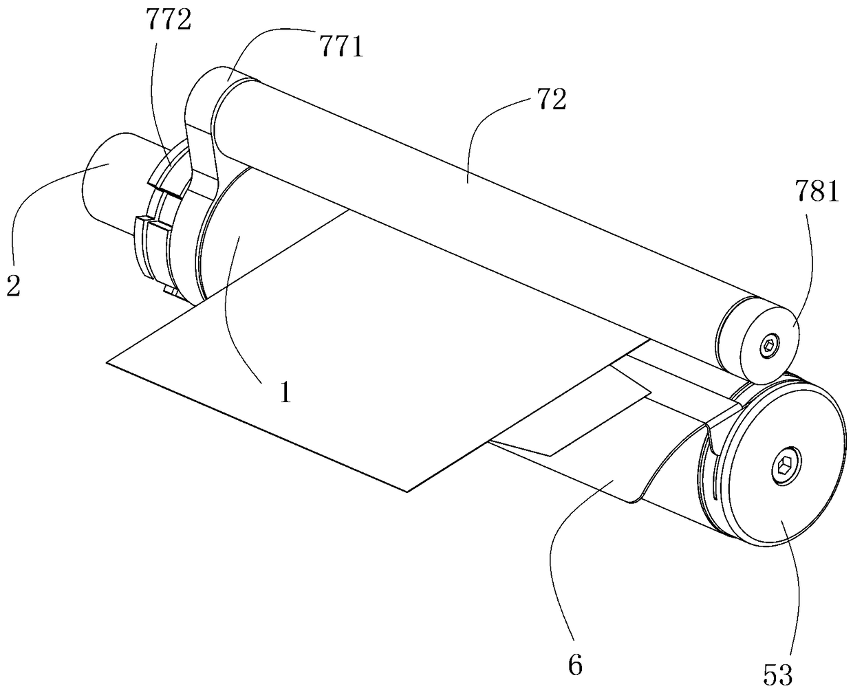
A pole plate passing roller structure

A technology of passing rollers and pole pieces, applied in the direction of structural parts, electrode manufacturing, battery electrodes, etc., can solve the unstable operation effect and overall tension control, affect the quality and qualification rate of lithium battery cells, the inertia of the roller movement, the movement Inertia increase and other problems, to achieve the effect of stable operation effect and tension control, ensure sensitivity, improve quality and pass rate

Pending Publication Date: 2018-12-11
GUANGDONG JITI SMART EQUIP CO LTD
View PDF0 Cites 3 Cited by
  • Summary
  • Abstract
  • Description
  • Claims
  • Application Information

AI Technical Summary

Problems solved by technology

[0003] At present, in the lithium battery manufacturing industry, it is necessary to use lithium battery cell winding equipment to complete the lithium battery cell winding link. Lithium battery cell winding equipment usually uses many rollers to carry and transmit pole pieces, and The installation method of the existing roller structure is to squeeze the inner ring of the supporting bearing to reduce the gap, so as to reduce the axial transmission, which causes the supporting bearing to be additionally subjected to axial pressure, causing the friction of the roller to rotate When the force increases and the friction increases, the inertia and inertia of the rollers will also increase, resulting in unstable operation effects and overall tension control, thus affecting the quality and pass rate of the lithium battery cells produced by winding.

Method used


Image

  • A pole plate passing roller structure
  • A pole plate passing roller structure
  • A pole plate passing roller structure

Examples


Embodiment Construction

[0030] The present invention will be described in further detail below in conjunction with the accompanying drawings and specific embodiments, and the implementation scope of the present invention is not limited thereto.

[0031] In describing the present invention, it should be understood that the terms "length", "width", "upper", "lower", "front", "rear", "left", "right", "vertical", The orientation or positional relationship indicated by "horizontal", "top", "bottom", "inner", "outer", etc. are based on the orientation or positional relationship shown in the drawings, and are only for the convenience of describing the present invention and simplifying the description, rather than Nothing indicating or implying that a referenced device or element must have a particular orientation, be constructed, and operate in a particular orientation should therefore not be construed as limiting the invention.

[0032] In addition, the terms "first" and "second" are used for descriptive p...


PUM


Abstract

A pole piece passing roller structure is disclosed, It comprises a first passing roller, a first central shaft and a first fixing assembly, wherein one end of the first passing roller inner wall is provided with a first rolling assembly, the other end of the first passing roller inner wall is provided with a second rolling assembly, the first passing roller is connected with the first central shaft through the first rolling assembly and the second rolling assembly, the second rolling assembly is connected with the first central shaft, and the first fixing assembly is connected with one end ofthe first central shaft. The pole piece passing roller structure realizes that the first bearing is not subjected to axial pressure and ensures that the first bearing is in a zero clearance state, sothat the first passing roller is subjected to less frictional force when rotated, the inertia of the first passing roller is small, avoiding the broken belt or wrinkling caused by excessive moment ofinertia of the pole piece, The axial movement of the first passing roller is reduced, a gap is arranged between the second bearingand the second step of the first central shaft, and the axial pressuregenerated by squeezing the second bearing is avoided, so that the second bearing is only used for supporting the first passing roller, so that the resistance of the first passing roller is smaller, and the quality and the yield of the lithium battery cell production are greatly improved.

Description

technical field [0001] The invention relates to the technical field of lithium battery manufacturing, in particular to a pole piece passing roller structure. Background technique [0002] Lithium-ion battery is a new type of high-energy battery successfully developed in the 20th century. Lithium-ion research began in the 1980s, entered the stage of industrialization in the 1990s, and developed rapidly. Lithium-ion batteries are favored by various industries due to their high specific energy, small size, and environmental friendliness. They are widely used in mobile phones, laptops and other digital products and new energy vehicles. [0003] At present, in the lithium battery manufacturing industry, it is necessary to use lithium battery cell winding equipment to complete the lithium battery cell winding link. Lithium battery cell winding equipment usually uses many rollers to carry and transmit pole pieces, and The installation method of the existing roller structure is to...

Claims


Application Information

Patent Timeline
Patent Type & Authority Applications(China)
IPC IPC(8): H01M10/0525H01M10/058H01M4/04
CPCH01M4/043H01M10/0525H01M10/058Y02E60/10Y02P70/50
Inventor 张祥领
Owner GUANGDONG JITI SMART EQUIP CO LTD
Why Eureka
Try Eureka