
Gas metering device and method for reporting gas metering information

A technology of gas metering and metering devices, which is applied in the direction of instruments, coin-operated equipment for distributing discrete items, coinless or similar appliances, etc., and can solve the problem of cloud platform, low utilization of information technology, observation display insertion and reading Card difficulty, inconvenient maintenance and other problems, to achieve the effect of convenient e-commerce, small size, easy installation and maintenance

Active Publication Date: 2017-01-18
BEIJING GAS GRP +1
View PDF6 Cites 0 Cited by
  • Summary
  • Abstract
  • Description
  • Claims
  • Application Information

AI Technical Summary

Problems solved by technology

[0003] However, the gas meter is usually installed on the gas pipeline of the family kitchen. Due to the limitation of the structure of the house or the direction of the gas pipeline, there are many restrictions on the installation position of the gas meter. In order to achieve more and more functions, many additional devices installed will inevitably cause the gas meter to have a complex structure and a large volume. For the staff of the gas company, maintenance is inconvenient. For users, if the installation In inconvenient places such as corners, it is also difficult to observe the display and insert and read the card
[0004] On the other hand, although the current gas meters integrate many functions, they are still limited to gas applications such as wireless meter reading, remote monitoring, security alarms, etc., and the interaction with users is not enough. At the same time, the latest cloud platform, information technology The utilization rate is not high

Method used


Image

  • Gas metering device and method for reporting gas metering information
  • Gas metering device and method for reporting gas metering information
  • Gas metering device and method for reporting gas metering information

Examples


Embodiment Construction

[0058] In order to describe the technical solution of the present invention more clearly, the present invention will be described in detail below in conjunction with the drawings and specific embodiments.

[0059] basic embodiment

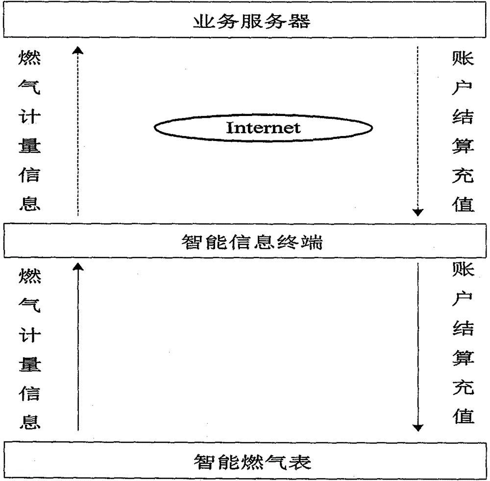
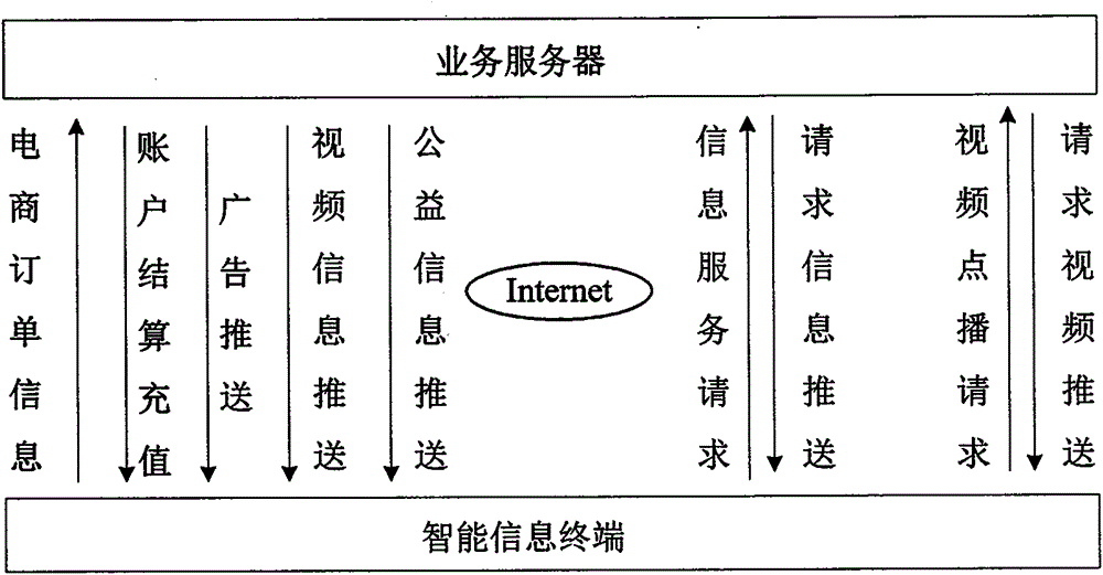
[0060] Figure 1A It is a schematic diagram of the metering device of the embodiment of the present invention. It can be seen that the metering device includes a separate gas meter (also called a gas meter, gas metering / measurement part, gas metering / measurement element, gas metering / measurement unit, etc.) and an intelligent gateway. The intelligent gateway includes a display (also called a display part, a display component, a display element or a display unit, etc.). It should be particularly noted that the above separation means that the gas meter and the intelligent gateway / display are not integrated together or are independent of each other, which is reflected in the form that the metering device is not a single overall shape. That is to sa...


PUM


Abstract

The invention provides a gas metering device and a gas information reporting method. The metering device comprises a gas meter and an independent display, wherein the gas meter comprises a gas input end, a gas output end, an electromechanical valve, a metering sensing module, a wireless transmission module, a wireless reception module, a CPU (Central Processing Unit) control module and a power supply module, which are all sealed in a metering device shell; the display is independently arranged away from the position of the gas meter. The gas meter does not have the display function of a conventional gas meter. Compared with the conventional gas meter, the gas meter is simple in structure, small in size and convenient to install and maintain; since the gas meter does not have the display function, the installation position of the gas meter can be more random and hidden, thus being beneficial to beautifying the site where the gas meter is located. The display can be independently arranged at other proper positions away from the gas meter. By means of the display which can be remote and movable, a user is convenient to observe, operate and manage the gas metering device. Furthermore, by means of the display and a cloud platform, electronic commerce is convenient to perform.

Description

technical field [0001] The invention relates to the field of gas metering, in particular to a gas metering device and a method for reporting gas metering information. Background technique [0002] With the continuous development of my country's social economy and the intensification of urban gas infrastructure construction in various places, my country's urban gas industry has developed rapidly, and urban gas consumption has rapidly increased. In this way, higher requirements are put forward for the measurement of gas. The gas meters currently produced in China can be divided into two types in terms of payment methods. One is to use first, and then pay after measurement. Representative; the other is prepaid, that is, the first payment can be used before the purchase, represented by the IC card gas meter. With the development of the Internet of Things technology, many smart gas meters and various remote meter reading systems have appeared. In the current wireless gas remote ...

Claims


Application Information

Patent Timeline
Patent Type & Authority Patents(China)
IPC IPC(8): G07F15/06
Inventor 李雅兰朱岩
Owner BEIJING GAS GRP
Learn More