optical network system
A technology of optical switch and optical input, applied in transmission system, electromagnetic network arrangement, electromagnetic wave transmission system, etc., which can solve the problems of updating, unable to perform FW continuously, unable to restart data transmission quickly, etc.
- Summary
- Abstract
- Description
- Claims
- Application Information
AI Technical Summary
Problems solved by technology
Method used
Image
Examples
Embodiment approach 1
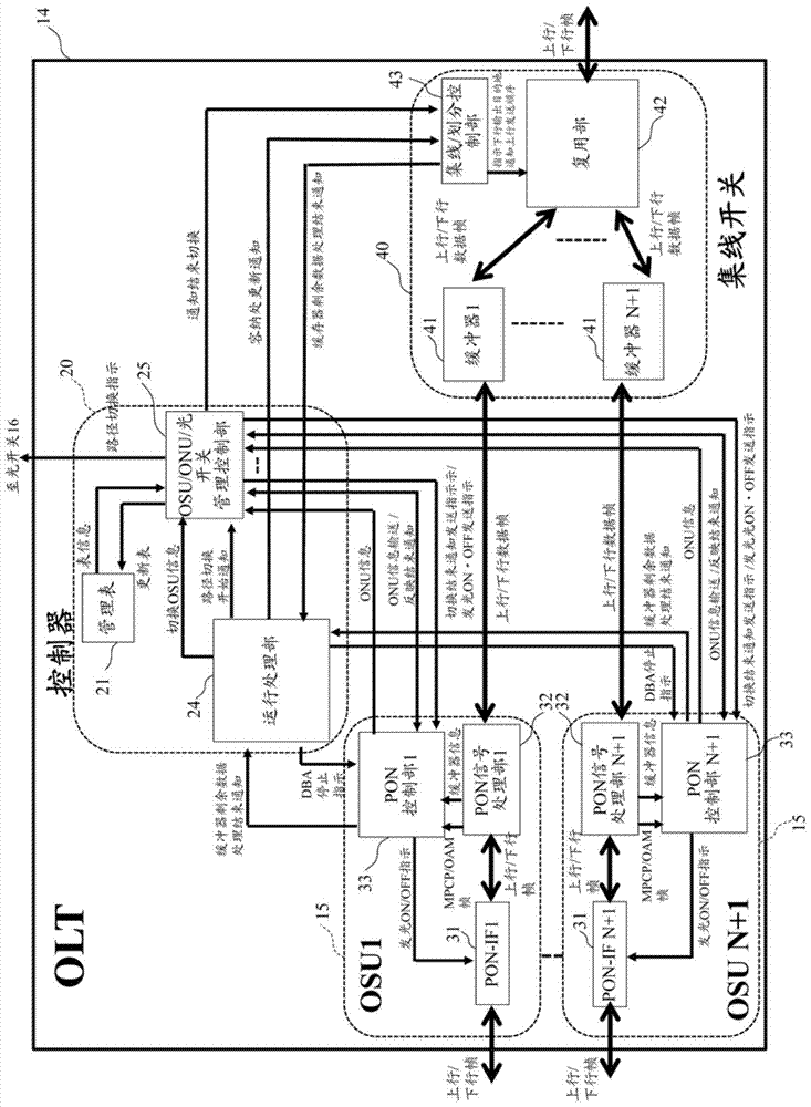
[0070] figure 1 A schematic configuration of an OLT included in the optical network according to Embodiment 1 is shown. The OLT 14 according to Embodiment 1 includes (N+1) OSUs 15 , one controller 20 for switching control, and one line switch 40 . Each OSU15 has a PON-IF31, a PON signal processing part 32, and a PON control part 33, the controller 20 has an OSU / ONU / optical switch management control part 25, an operation processing part 24, and a management table 21, and the hub switch 40 has a hub / Division control unit 43 , multiplexing unit 42 and (N+1) buffers 41 . The buffer 41 has an uplink buffer and a downlink buffer. In addition, descriptions of configurations that are unnecessary for the description are omitted.
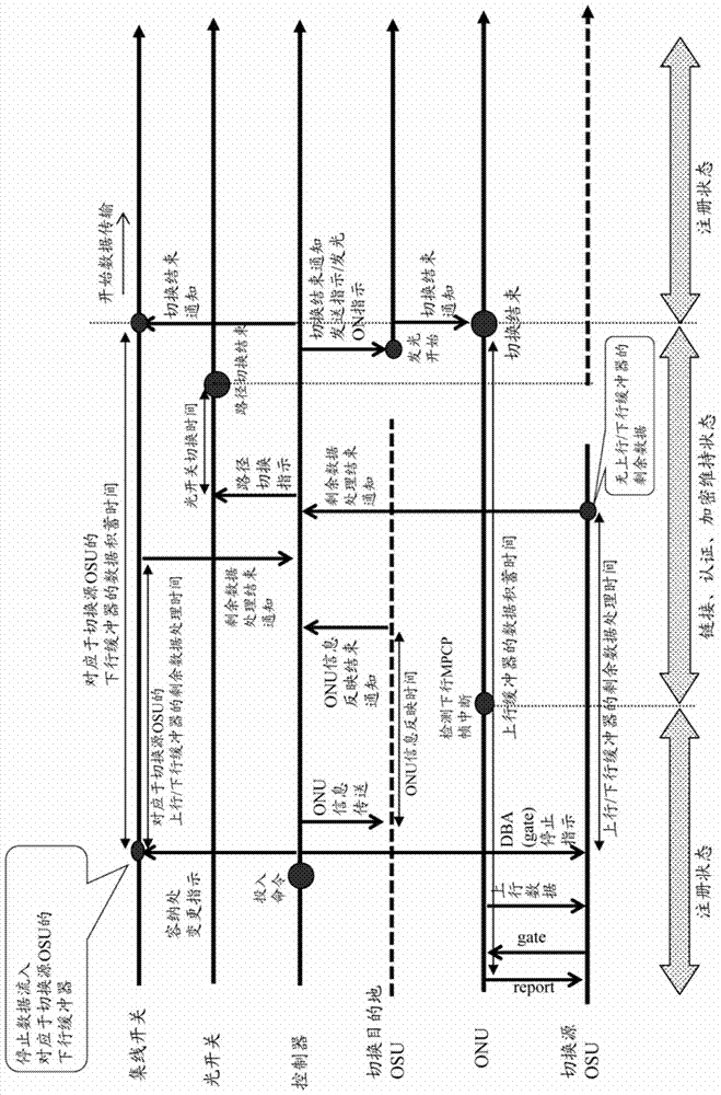
[0071]The OLT 14 of this configuration is assumed to be applicable to a PON protection system with redundant OSU 15 using an optical switch 16. When updating the FW of the OSU 15 in such a system, the connection destination OSU 15 of the ONU 17 subordin...
Embodiment approach 2
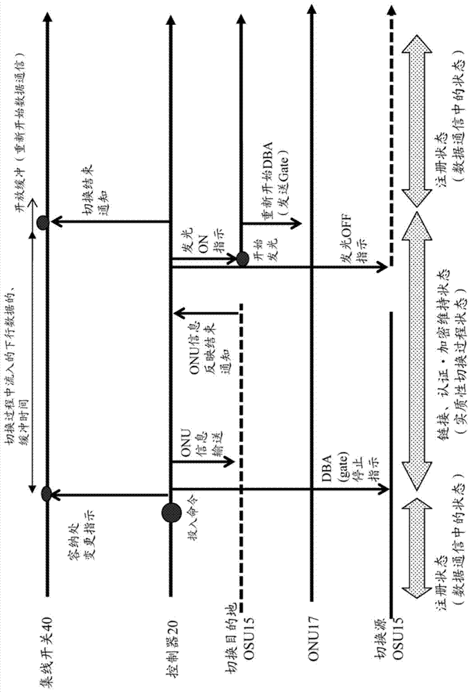
[0105] Figure 4 An example in which the switching sequence and the OLT configuration in the first embodiment are applied to a PON system using the optical switch 16 is shown. This embodiment is based on Figure 24 In the N:1 protection-based system with N=2, two OSU15_1 and OSU15_2 among the three OSU15 in this OLT14 are normal system OSUs, and one OSU15_3 is a redundant system OSU. Supposing A=32, when each normal system OSU15_1~15_2 is normal, through 2*3 optical switch 16 and PON line 1·PON line 2 respectively, accommodate 32 ONU17, redundant system OSU15_3 passes 2*3 optical switch 16 not Connect with any PON line. When normal, two normal OSUs 15_1 and 15_2 notify the ONU information of the subordinate ONU 17 to the controller 20 respectively. As a result, the controller 20 holds such Figure 5 Management Table 21 shown.
[0106] In such a system, for example, when updating the FW of OSU15_2, first, in order to switch the connection destination OSU of ONU17 (ONU33 to ...
Embodiment approach 3
[0110] Figure 8 A case where this OLT 14 and a switching sequence are applied to N:1 protection configured differently from Embodiment 2 is shown. In this embodiment, one OLT 14, one N×1 optical switch 16, and N B:2 optical splitters 18 (1≤B≤A are used. However, in consideration of cost, B>A is also possible technically. ), ONU17 below A×N units. N of the N+1 OSUs 15 in this OLT 14 is a normal system OSU 15 (OSU1-OSUN), and the remaining one is a redundant system OSU (OSUN+1). The normal system OSU15 of N units is respectively connected to one port on both sides of N B:2 optical splitters 18 through a PON line, and one redundant system OSU15 is connected to one side of N×1 optical switch 16 through an optical fiber (input side). The other port on both sides of the N B:2 optical splitters 18 is respectively connected to the N side of the N×1 optical switch 16 through an optical fiber (called a preliminary optical fiber), and the B side of the B:2 optical splitter 18 passes ...
PUM
 Abstract
Description
Claims
Application Information
 - R&D
- Intellectual Property
- Life Sciences
- Materials
- Tech Scout
- Unparalleled Data Quality
- Higher Quality Content
- 60% Fewer Hallucinations
Browse by: Latest US Patents, China's latest patents, Technical Efficacy Thesaurus, Application Domain, Technology Topic, Popular Technical Reports.
© 2025 PatSnap. All rights reserved.Legal|Privacy policy|Modern Slavery Act Transparency Statement|Sitemap|About US| Contact US: help@patsnap.com


