Switching regulator including charge pump

A power supply and switching technology, which is applied in the directions of conversion equipment without intermediate conversion to AC, output power conversion devices, electrical components, etc., can solve the problems of reduced power conversion efficiency of the switching power supply 100 and the like

Inactive Publication Date: 2014-07-16
RICHTEK TECH
View PDF3 Cites 4 Cited by
  • Summary
  • Abstract
  • Description
  • Claims
  • Application Information

AI Technical Summary

Problems solved by technology

However, in the prior art, if the high voltage withstand capability of the power switch M is improved, the power conversion efficiency of the switching power supply 100 will often be reduced; in addition, under the condition of high voltage operation, the inductor current in the power stage circuit 110 is relatively large. High, under certain load conditions, there will be audio noise (audio noise)

Method used


Image

  • Switching regulator including charge pump
  • Switching regulator including charge pump
  • Switching regulator including charge pump

Examples


Embodiment Construction

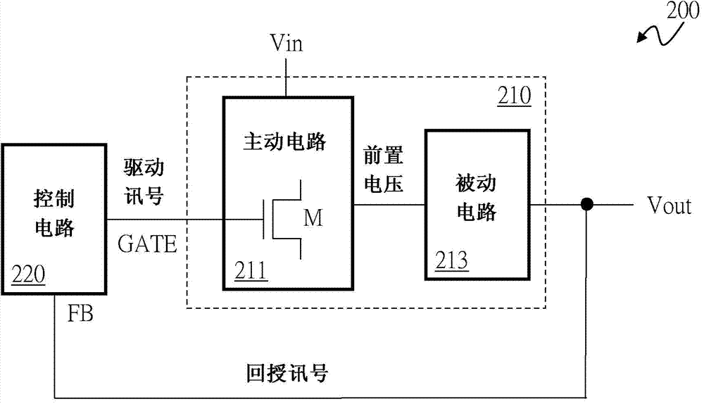
[0026] see figure 2 , showing a first embodiment of the present invention. Such as figure 2 As shown, the switch mode power supply 200 includes a power stage circuit 210 and a control circuit 220 . The power stage circuit 210 switches the power switch M to convert the input voltage Vin to the output voltage Vout according to a driving signal GATE. The control circuit 220 is coupled to the power stage circuit 210 and generates the driving signal GATE according to the feedback signal FB. The power stage circuit 210 includes an active circuit 211 and a passive circuit 213 . The active circuit 211 includes a power switch M and an inductor (not shown, details will be described later) for receiving the input voltage Vin and the driving signal GATE, and converting the input voltage Vin into a pre-voltage. The passive circuit 213 is coupled to the active circuit 211 and includes a charge pump (not shown, described in detail later) to convert the pre-voltage into the output volta...


PUM


Abstract

The present invention discloses a switching regulator including a charge pump. The switching regulator converts an input voltage to an output voltage. The switching regulator includes: a power stage circuit, which switches at least one power switch thereof according to a driving signal to convert the input voltage to the output voltage; and a control circuit, which is coupled to the power stage circuit, for generating the driving signal according to a feedback signal. The power stage circuit includes: an active circuit, which includes the power switch and at least one inductor, and is controlled by a driving signal to convert the input voltage to a middle voltage; and a passive circuit, which is coupled to the active circuit, and includes a charge pump for converting the middle voltage to the output voltage.

Description

technical field [0001] The present invention relates to a switching power supply with a charge pump, in particular to a switching power supply that reduces the demand for a withstand voltage of a power switch. Background technique [0002] figure 1 A schematic diagram of a typical switching power supply 100 is shown. Such as figure 1 As shown, the switching power supply 100 includes a power stage circuit 110 and a control circuit 120 . The control circuit 120 generates the operation signal GATE according to the feedback signal FB related to the output voltage Vout to operate the power switch M in the power stage circuit 110 to convert the input voltage Vin to the output voltage Vout. The power stage circuit 110 is a step-up power stage circuit, including a power switch M, an inductor L, and a diode element D. As shown in FIG. Its mode of operation is well known to those skilled in the art and will not be repeated here. [0003] When the aforementioned switching power su...

Claims


Application Information

Patent Timeline
Patent Type & Authority Applications(China)
IPC IPC(8): H02M3/07
CPCH02M3/07H02M3/155
Inventor 陈庆宇林锋玮金光才
Owner RICHTEK TECH
Why Eureka
Try Eureka