A DC circuit breaker topology with bidirectional blocking function

A technology of DC circuit breaker and topology, which is applied in the field of DC circuit breaker topology, can solve the problems of inability to shut down the current, and the difficulty of breaking time to meet the DC transmission system, and achieve the effects of low withstand voltage demand, light weight and small quantity

Active Publication Date: 2019-01-25
INST OF ELECTRICAL ENG CHINESE ACAD OF SCI
View PDF6 Cites 0 Cited by
  • Summary
  • Abstract
  • Description
  • Claims
  • Application Information

AI Technical Summary

Problems solved by technology

Different from the AC system, the current of the DC system does not have a natural zero-crossing point, so the natural zero-crossing point of the current cannot be used in the DC system like the AC system. Therefore, the breaking of the DC current has always been a problem worth studying. Subject
The hybrid circuit breaker manufactured by using this principle has special requirements for mechanical switches, and it is difficult to meet the requirements of the DC transmission system in terms of breaking time.

Method used


Image

  • A DC circuit breaker topology with bidirectional blocking function
  • A DC circuit breaker topology with bidirectional blocking function
  • A DC circuit breaker topology with bidirectional blocking function

Examples


Embodiment 1

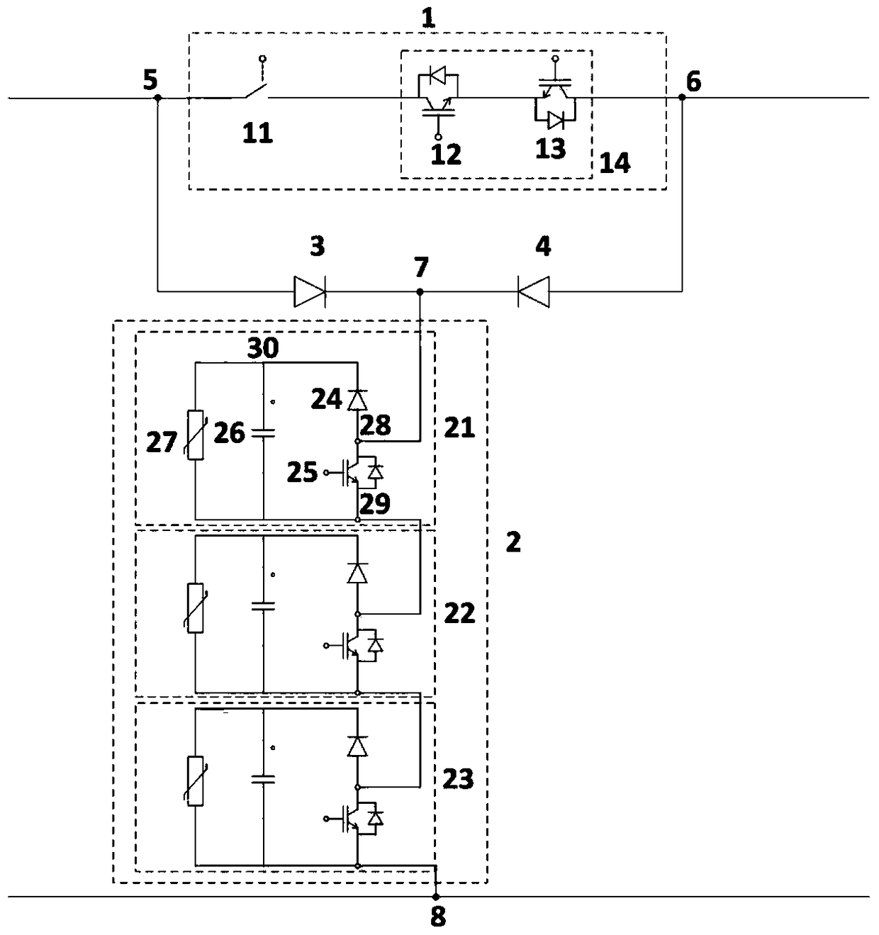
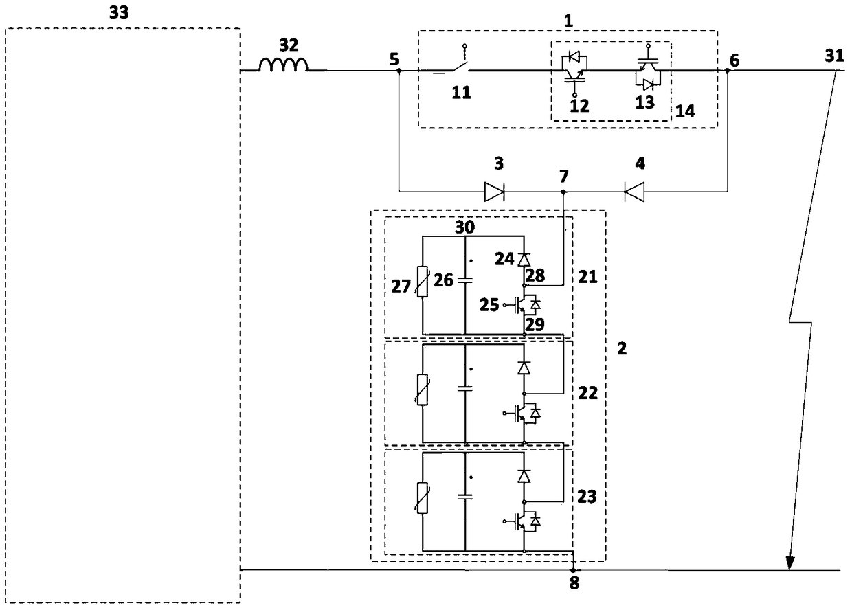
[0027] figure 2 Shown is a specific embodiment of the DC circuit breaker connected to the DC line, wherein the first lead-out terminal 5 of the DC circuit breaker is connected to one end of the inductor 32 on the DC line, and the other end of the inductor is connected to the positive pole of the converter station 33 , the second lead-out terminal 6 of the DC circuit breaker is connected to the short-circuit point 31, and the third lead-out terminal 8 of the DC circuit breaker is connected to the negative DC bus. The semiconductor device group 14 in the main circuit module is composed of a first IGBT module 12 and a second IGBT module 13 in reverse series. The fault current blocking module is composed of a first submodule 21 , a second submodule 22 and a third submodule 23 cascaded.

Embodiment 2

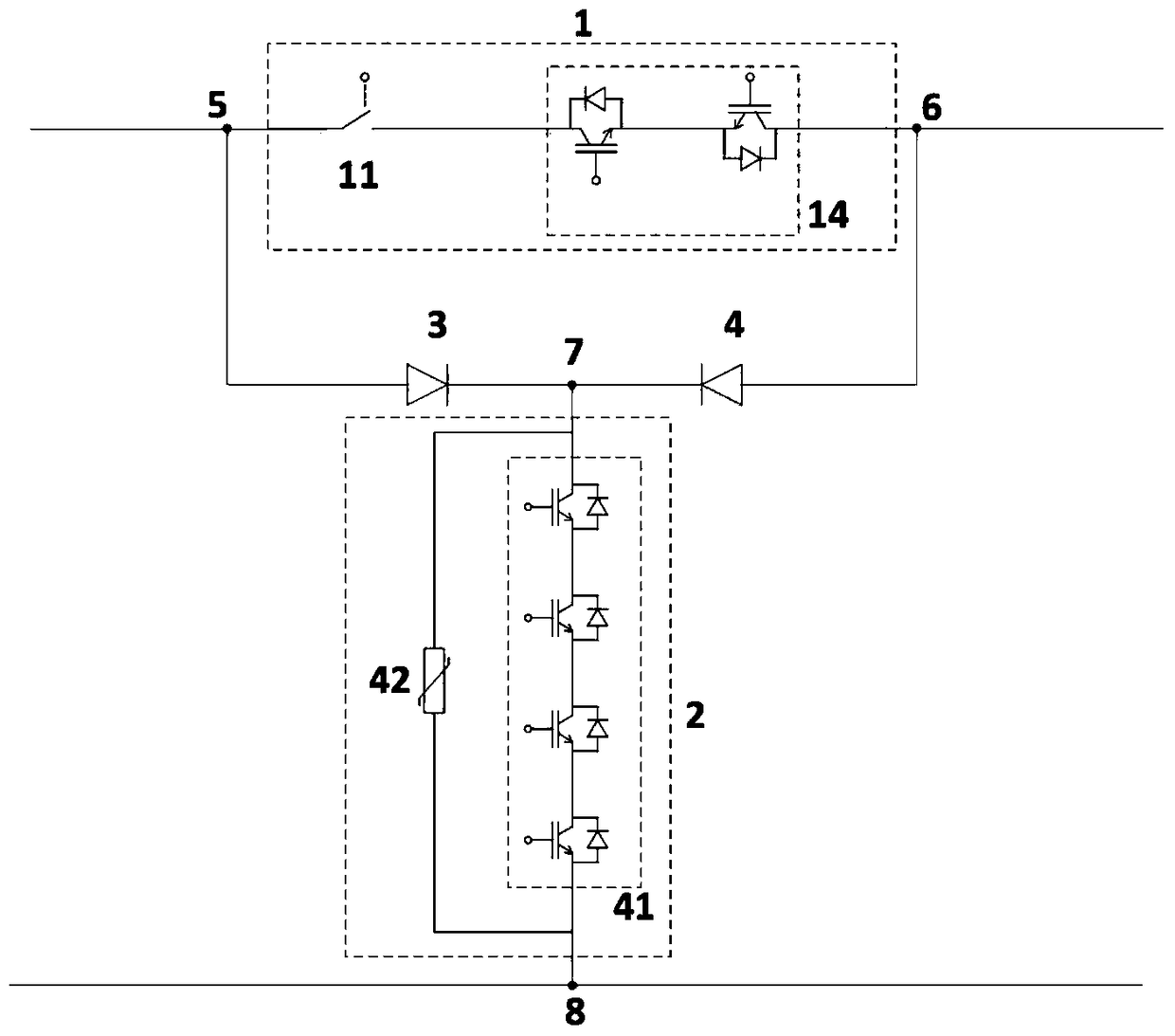
[0029] image 3 Shown is another implementation of the fault current blocking module. The fault current blocking module 2 is composed of a fully-controlled semiconductor device group 41 connected in parallel with an arrester 42, and the fully-controlled semiconductor device group 41 is composed of multiple IGBTs connected in series.


PUM


Abstract

A direct current breaker topology with a bidirectional blocking function is disclosed. The direct current breaker topology comprises a main loop module (1), a fault current blocking module (2), a first diode group (3) and a second diode group (4); the first leading-out terminal of the main loop module (1) is connected with the positive electrode of the first diode group (3), and the connecting point between the first leading-out terminal of the main loop module and the positive electrode of the first diode group is used as the first leading-out terminal (5) of the direct current breaker topology; the second leading-out terminal of the main loop module (1) is connected with the positive electrode of the second diode group (4), and the connecting point between the second leading-out terminal of the main loop module and the positive electrode of the second diode group is used as the second leading-out terminal (6) of the direct current breaker topology; the negative electrode of the first diode group (3) is connected with the negative electrode of the second diode group (4); and the second leading-out terminal of the fault current blocking module (2) is used as the third leading-out terminal (8) of the direct current breaker topology.

Description

technical field [0001] The invention relates to a DC circuit breaker topology. Background technique [0002] Fast DC circuit breaker is one of the key equipment to ensure the stable, safe and reliable operation of DC power transmission and distribution system and DC grid system. Different from the AC system, the current of the DC system does not have a natural zero-crossing point, so the natural zero-crossing point of the current cannot be used in the DC system like the AC system. Therefore, the breaking of the DC current has always been a problem worth studying. topic. [0003] At present, there are usually two ways to break DC current. The first is a pure power electronic circuit breaker, such as the patent CN102870181A applied by ABB Company, which can turn off power electronic devices with high power and directly break DC current. Although the solid-state circuit breaker manufactured by this principle can meet the requirements of the multi-terminal flexible DC system i...

Claims


Application Information

Patent Timeline
Patent Type & Authority Patents(China)
IPC IPC(8): H02H3/087
Inventor 朱晋刘单华尹靖元韦统振
Owner INST OF ELECTRICAL ENG CHINESE ACAD OF SCI
Why Eureka
Try Eureka