Power supply with power factor correction circuit

A power factor correction, power supply technology, applied in output power conversion devices, high-efficiency power electronic conversion, conversion of DC power input to DC power output, etc., can solve the burden of increasing costs, cannot be independently controlled, and many electronic components and other problems, to achieve the effect of reducing the complexity of the manufacturing process, reducing the demand for withstand voltage, and reducing the demand for components

Active Publication Date: 2019-01-15
MEAN WELL ENTERPRISES
View PDF3 Cites 0 Cited by
  • Summary
  • Abstract
  • Description
  • Claims
  • Application Information

AI Technical Summary

Problems solved by technology

However, the three-phase power factor circuit is difficult to control the coupling between the three phases
In a single-phase power factor circuit, if the load is equivalent to a resistance, the input power factor is 1, while in a three-phase power factor circuit, even if the load is equivalent to a resistance, the power factor is often difficult to be a satisfactory value, the reason The reason is that the three-phase power factor circuit cannot take into account the three-phase input current at the same time, and cannot independently control the input current of any phase to be a sinusoidal waveform.
Conventional technology has improved this problem and introduced many typical three-phase power factor circuits. However, these typical circuits require too many electronic components, and the control is complicated. The demand for the withstand voltage of the components is high, which increases the cost. burden

Method used


Image

  • Power supply with power factor correction circuit
  • Power supply with power factor correction circuit
  • Power supply with power factor correction circuit

Examples


Embodiment Construction

[0044] In order to further explain the technical means and effects of the present invention to achieve the intended purpose of the invention, the following is a specific implementation of a power supply with a power factor correction circuit proposed according to the present invention in conjunction with the accompanying drawings and preferred embodiments. , structure, feature and effect thereof, detailed description is as follows.

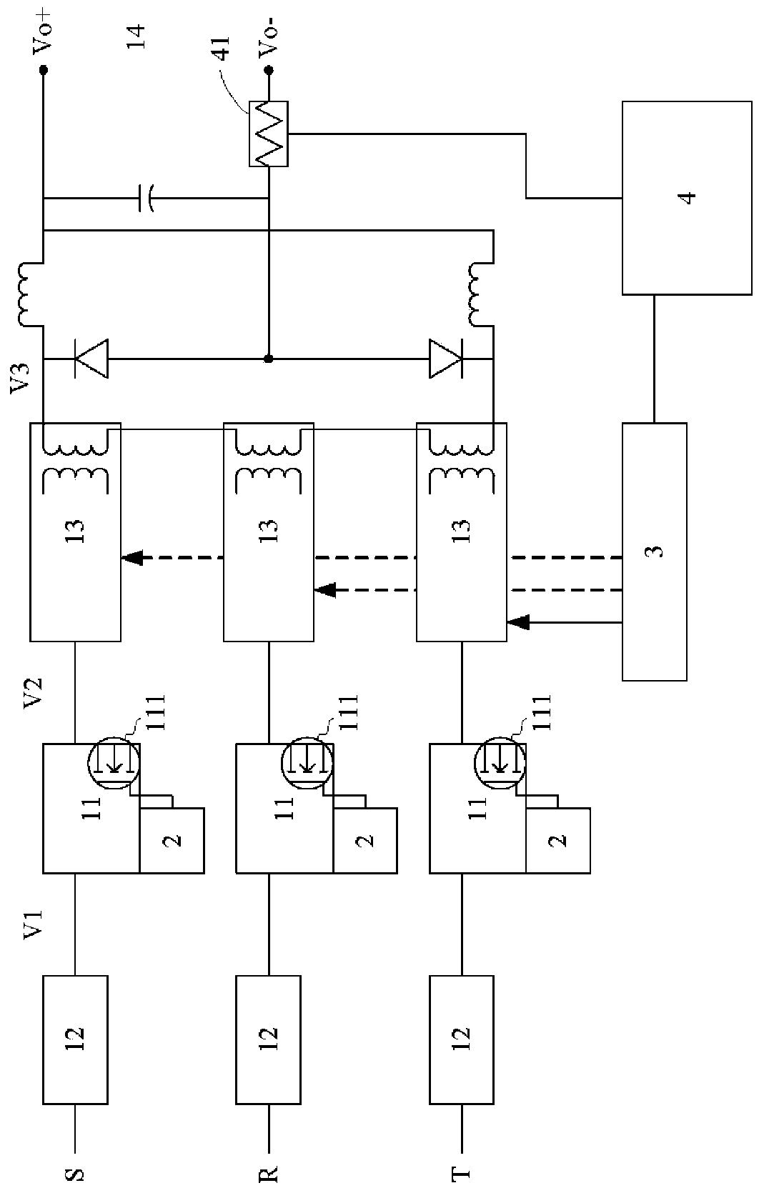
[0045] Please refer to image 3 , a structural diagram of a power supply with a power factor correction circuit in the present invention. Such as image 3 As shown, the present invention is a power supply with a power factor correction circuit, which can receive the voltage of three-phase voltage, and includes: three rectification modules, which respectively receive the first phase voltage S and the second phase voltage of the three-phase voltage voltage R and the third phase voltage T, and each rectification module further includes: a filter 12, ...


PUM


Abstract

The invention discloses a power supply device having a power factor correction circuit, which is capable of receiving the voltage of three-phase voltage. The power supply device having the power factor correction circuit comprises three rectification modules which are respectively receiving first phase voltage, second phase voltage and third phase voltage of the three-phase voltage; each rectification module comprises a filter which is used for receiving one voltage of the three phase voltage and outputting filtering voltage, a single-phase power factor correction circuit which is coupled to the filter for receiving the filtering voltage and outputting correction voltage; and the each rectification module also comprises a main transistor, a converter, at least one power factor correction controller, and a simulation controller; the converter is coupled to the output terminal of the single-phase power factor correction circuit and is connected to the voltage output terminal; the power factor correction controller is connected to a main transistor; and the simulation controller is connected to the converter. The power supply device having a power factor correction circuit eliminates the mutual interference between the rectification modules, requires less quantity of members by comparing with the traditional three-phase parallel connection power factor correction circuit, saves the cost without influencing the result, and guarantees the quality.

Description

technical field [0001] The present invention relates to a single-phase buck-boost PFC circuit, especially a buck-boost PFC circuit, which can improve the buck-boost and improve its efficiency. Background technique [0002] Power factor refers to the relationship between effective power and total power consumption, that is, the ratio of effective power divided by total power consumption. Generally speaking, power factor can be used to measure the degree of power utilization. The larger the power factor value, the higher the power utilization rate. Power factor correctors applied to power supplies are mostly used to control and adjust the time and waveform of AC current input to make it as consistent as possible with the DC voltage waveform, so that the power factor value is close to 1, and avoid power equipment system consumption. Electricity exceeds its specification, creating unnecessary disturbances. [0003] From the above, it can be seen that low power factor means low...

Claims


Application Information

Patent Timeline
Patent Type & Authority Patents(China)
IPC IPC(8): H02M1/42H02M3/335
CPCY02B70/10Y02P80/10
Inventor 简鹏辉
Owner MEAN WELL ENTERPRISES
Why Eureka
Try Eureka