Shutter
A technology of blinds and sheets, which is applied in the field of daily necessities, can solve problems such as easy misalignment of sheets and system jamming, and achieve the effects of strong reproducibility, high work reliability, operability and practicability
- Summary
- Abstract
- Description
- Claims
- Application Information
AI Technical Summary
Problems solved by technology
Method used
Image
Examples
Embodiment 1
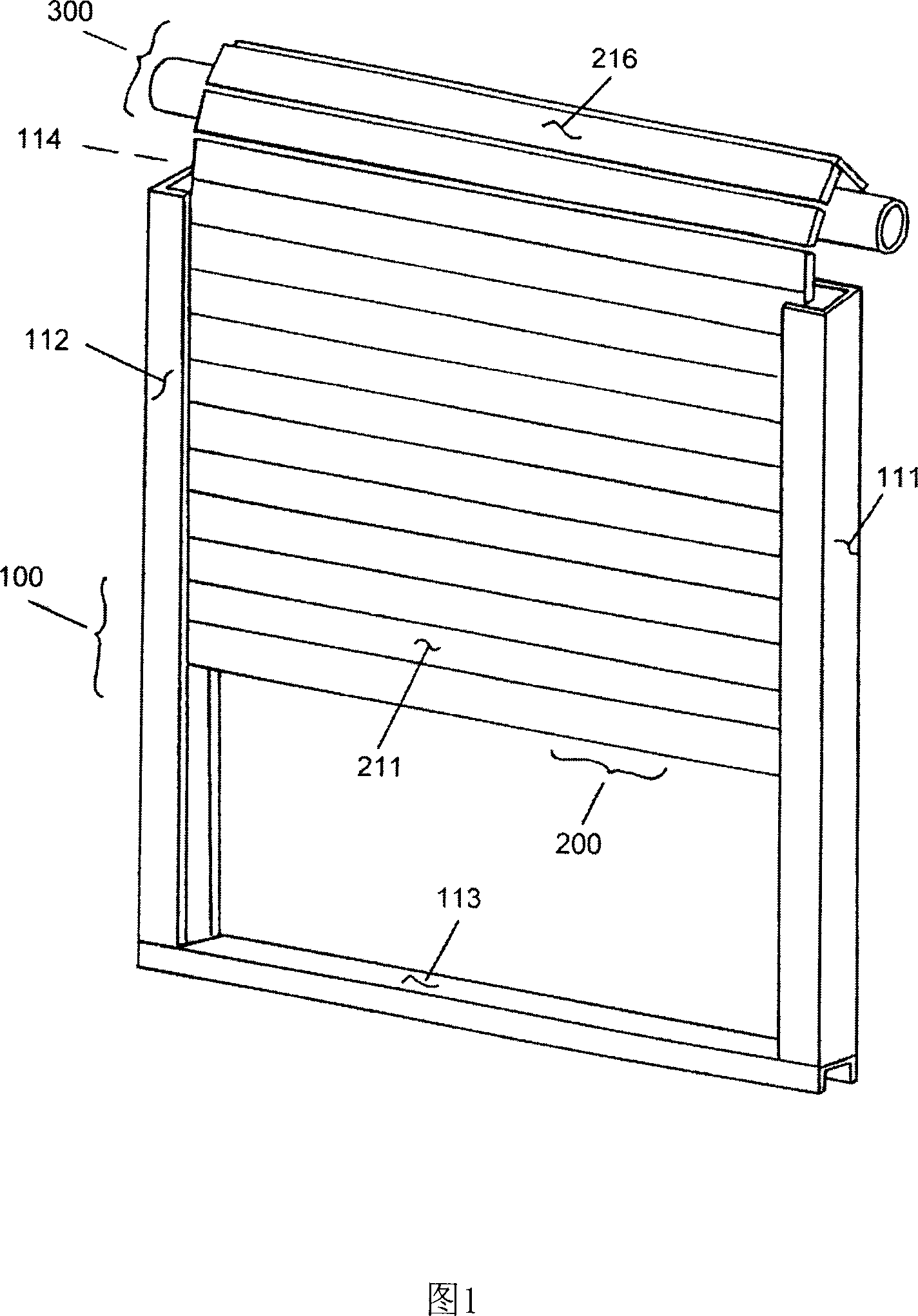
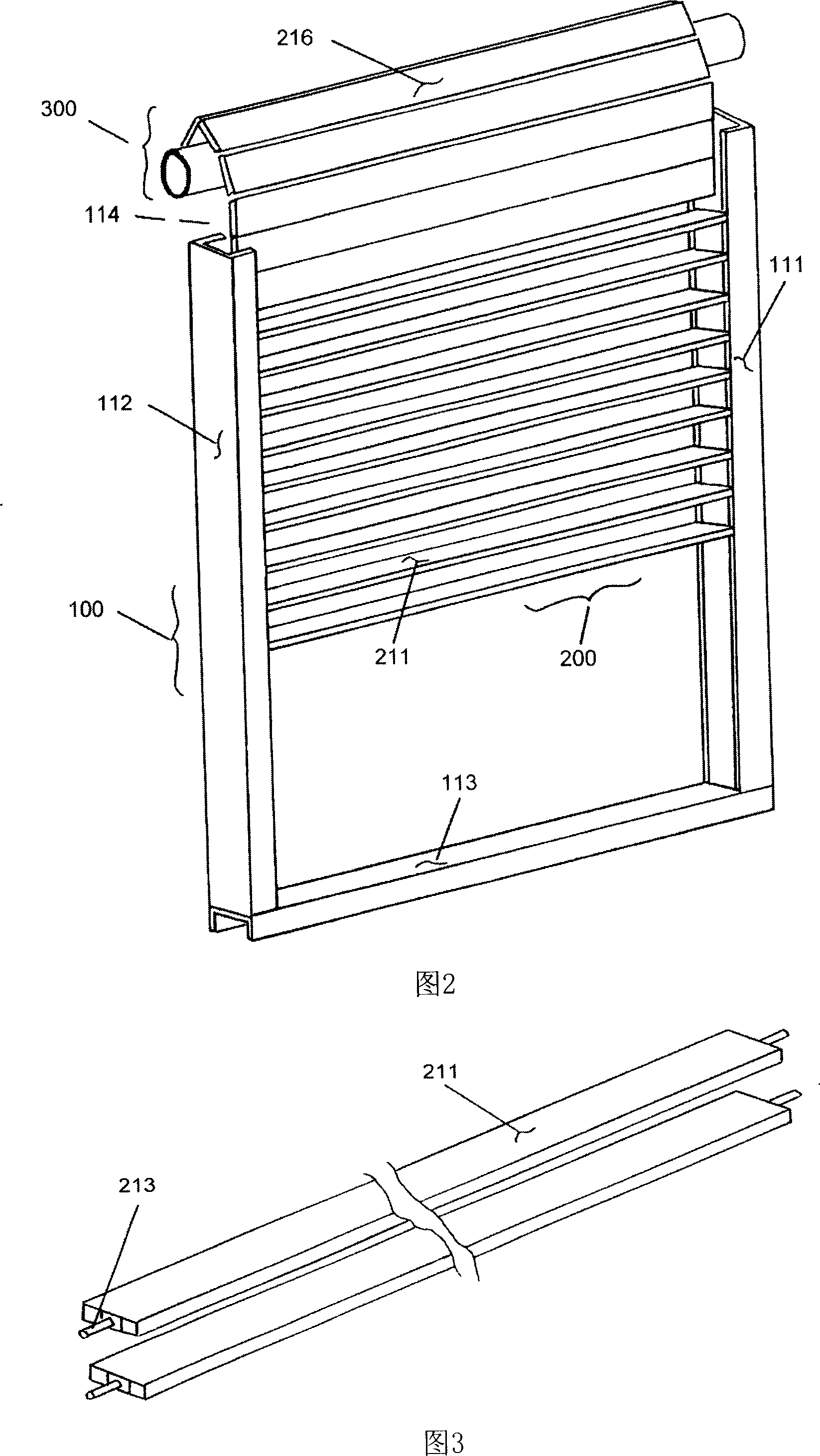
[0063] according to figure 1 , the shutter in this embodiment includes a group of leaf pieces 211 arranged in sequence and synchronously rotating, a frame body 100 and a storage mechanism 300, the leaf pieces 211 are arranged in the frame body 100, and the frame body 100 is installed on a relatively fixed On a covered object, such as the outer surface of a door or window.
[0064] Such as figure 1 and figure 2 As shown, the frame body 100 is composed of a right frame 111, a left frame 112, a lower frame 113 and an upper frame 114 (covered by the louver main body 200). The frame body 100 provides rigidity and strength for the entire louver, and is also the The interface between the shutter and the building, in other words, the whole of the present invention is fixedly installed on the outer surface of the protected door or window through the frame body 100 . In this frame body 100, the left frame 112 and the right frame 111 are indispensable, and as for the upper frame 114 ...
Embodiment 2
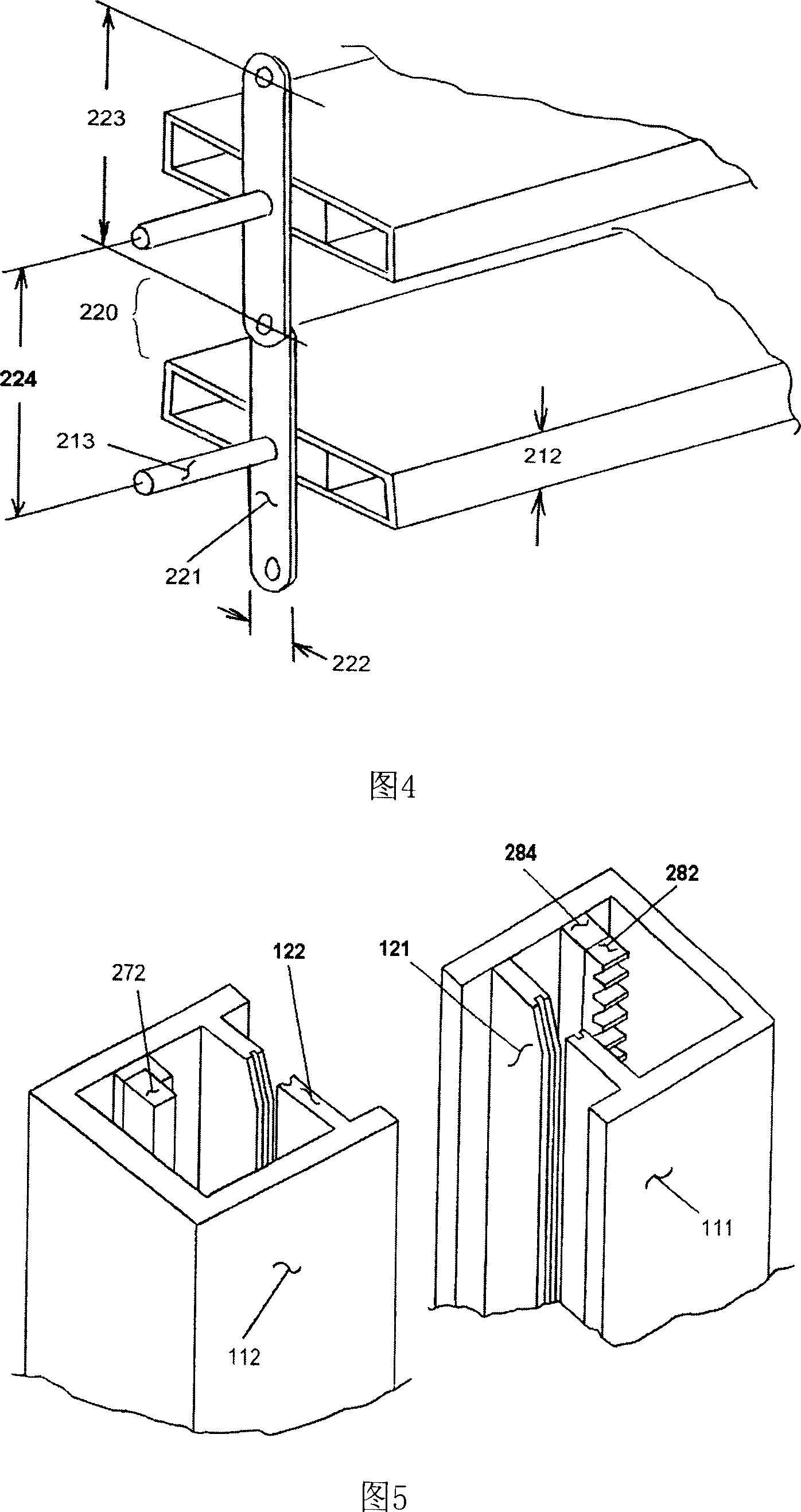
[0084] according to Figure 11The main difference between this embodiment and Embodiment 1 is that in this embodiment, another available chain 240 structure is reflected. Similarly, the width 242 of a single chain element 241 cannot exceed the thickness 212 of the sheet. The main difference between this chain 240 and the aforementioned chain 220 is that the length of each unit of the chain 240 is only about half of the unit length of the chain 220, and the chain 240 has two hole positions, and the distance between them is exactly the same as that on the chain element 221, The distance between two adjacent holes. In this way, it can be ensured that the distance 244 between the sheets is equal to the distance 224 in Embodiment 1. This kind of chain 240 is more elastic when it is wound on the storage mechanism 300 .
[0085] The principles and structures of other parts are the same or similar to those described in Embodiment 1, and will not be repeated here.
Embodiment 3
[0087] according to Figure 12 , The main difference between this embodiment and Embodiment 1 or Embodiment 2 is: in this embodiment, among the meshing points of the rack 282 and the plurality of gears 281, the horizontal positions of the meshing points can be staggered from each other.
[0088] Since the diameter 283 of the slave wheel 281 is greater than the thickness 212 of the sheet 211, it is likely that the gear 281 carried on the second layer of the sheet 211 on the central shaft 201 will conflict with the gear 281 of the first layer. To avoid this conflict, the position of the second ring gear 281 on the shaft 213 must deviate from the position of the first ring gear 281 on the shaft 213, such as Figure 12 As shown, a misalignment gap is set between the nth ring gear set and the n+1th ring gear set.
[0089] The principles and structures of other parts are the same or similar to those described in Embodiment 1 or Embodiment 2, and will not be repeated here.
PUM
 Abstract
Description
Claims
Application Information
 - R&D
- Intellectual Property
- Life Sciences
- Materials
- Tech Scout
- Unparalleled Data Quality
- Higher Quality Content
- 60% Fewer Hallucinations
Browse by: Latest US Patents, China's latest patents, Technical Efficacy Thesaurus, Application Domain, Technology Topic, Popular Technical Reports.
© 2025 PatSnap. All rights reserved.Legal|Privacy policy|Modern Slavery Act Transparency Statement|Sitemap|About US| Contact US: help@patsnap.com


