
Cutting gear case with two side hydraulic oil ways

A technology of hydraulic oil circuit and gear box, applied in the direction of belt/chain/gear, components with teeth, transmission parts, etc., can solve the problem that the hydraulic cylinder of the cutting gear box cannot be independently controlled, and reduce the risk factor of high pressure. , The pressure loss is small, the effect of reducing the oil supply pressure

Pending Publication Date: 2020-08-07
NANJING HIGH SPEED & ACCURATE GEAR GRP
View PDF0 Cites 0 Cited by
  • Summary
  • Abstract
  • Description
  • Claims
  • Application Information

AI Technical Summary

Problems solved by technology

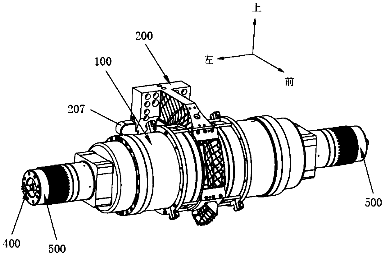
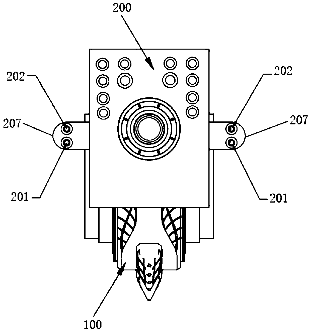
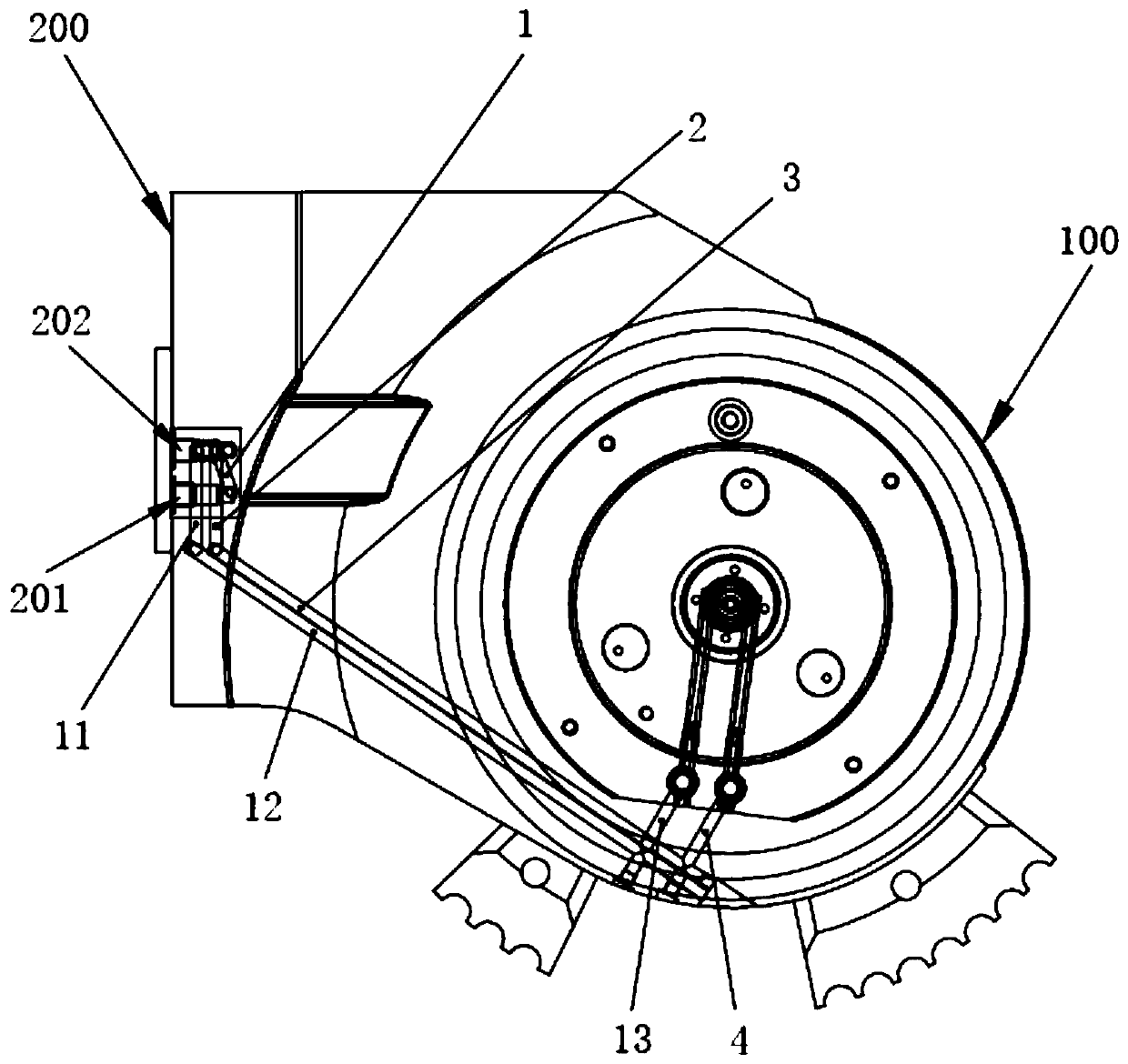
[0008] The purpose of the present invention is to provide a cutting gear box with hydraulic oil circuits on both sides to solve the problem in the prior art that the hydraulic cylinders on both sides of the cutting gear box cannot be independently controlled

Method used


Image

  • Cutting gear case with two side hydraulic oil ways
  • Cutting gear case with two side hydraulic oil ways
  • Cutting gear case with two side hydraulic oil ways

Examples


Embodiment Construction

[0067] The present invention will be further described in detail below in conjunction with the accompanying drawings and embodiments. It should be understood that the specific embodiments described here are only used to explain the present invention, but not to limit the present invention. In addition, it should be noted that, for the convenience of description, only some structures related to the present invention are shown in the drawings but not all structures. The components of the embodiments of the invention generally described and illustrated in the figures herein may be arranged and designed in a variety of different configurations.

[0068] Accordingly, the following detailed description of the embodiments of the invention provided in the accompanying drawings is not intended to limit the scope of the claimed invention, but merely represents selected embodiments of the invention. Based on the embodiments of the present invention, all other embodiments obtained by per...


PUM


Abstract

The invention discloses a cutting gear case with two side hydraulic oil ways. The cutting gear case comprises a case body, a base, planet carriers and high-pressure oil pipes. The base is arranged onthe case body and used for installing the cutting gear case, and oil inflow holes and oil return holes are formed in the two sides of the base. The planet carriers are arranged at the two ends in thecase body. The cutting gear case is provided with first oil inflow oil ways and first oil return oil ways, one end of each first oil inflow oil way is connected with the corresponding oil inflow hole,and each planet carrier is provided with a second oil inflow oil way connected with the other end of the corresponding first oil inflow oil way; and one end of each first oil return oil way is connected with the corresponding oil return hole, and each planet carrier is provided with a second oil return oil way connected with the other end of the corresponding first oil return oil way. The high-pressure oil pipes are connected with the planet carriers and comprise oil inflow cavities and oil return cavities, the oil inflow cavities communicate with the second oil inflow oil ways, and the oil return cavities communicate with the second oil return oil ways. By the adoption of the cutting gear case, high-pressure oil cylinders on the two sides can be independently controlled, the high-pressure oil pipes are provided with the oil inflow cavities and the oil return cavities at the same time, the structure is simplified, and the sealing performance is good.

Description

technical field [0001] The invention relates to the technical field of gear boxes, in particular to a cutting gear box with hydraulic oil passages on both sides. Background technique [0002] The main function of the built-in hydraulic oil circuit of the cutting gearbox of the bolter miner is to provide high-pressure support for the extension and loading of the hydraulic cylinders on both sides of the cutting gearbox, and to provide continuous and stable pressure output for the hydraulic cylinders. The built-in hydraulic oil circuit of the existing bolter cutting gear box has only one high-pressure oil inlet and return port, and supplies oil to the hydraulic cylinders on both sides at the same time. The disadvantages of the built-in hydraulic oil circuit arrangement of the cutting gear box are: [0003] 1. The independent control of the hydraulic cylinders on both sides of the gearbox cannot be realized; [0004] 2. When the oil flows from the main oil inlet to the branches...

Claims


Application Information

Patent Timeline
IPC IPC(8): F16H57/08F16H57/029F16H61/4008
CPCF16H57/029F16H57/08F16H61/4008F16H2057/02086
Inventor 王颖米中生刘增民陈春辉何伟炜
Owner NANJING HIGH SPEED & ACCURATE GEAR GRP
Learn More