Eureka AIR delivers breakthrough ideas for toughest innovation challenges, trusted by R&D personnel around the world.

Protection device for filter element type high temperature iron removal filter

A protection device and filter technology, applied in the direction of filtration separation, chemical instruments and methods, separation methods, etc., can solve the problems affecting the life of filters and filter elements, filter element damage, large thermal stress, etc., to ensure safe operation, Extended service life, wide range of effects

Active Publication Date: 2016-04-20
CEEC JIANGSU ELECTRIC POWER DESIGN INST
View PDF5 Cites 0 Cited by
  • Summary
  • Abstract
  • Description
  • Claims
  • Application Information

AI Technical Summary

Problems solved by technology

In order to ensure thorough backwashing, air-water backwashing is generally used for filter backwashing. However, due to the high operating temperature and pressure of the iron-removing filter, direct backwashing with air-water at room temperature will cause the main body of the iron-removing filter and the The temperature of the element changes sharply, resulting in a large thermal stress, which seriously affects the life of the filter and the filter element, and even directly leads to the destruction of the filter element. Therefore, cooling measures must be taken before backwashing the iron removal filter
[0006] In addition, the iron removal filter after outage and backwashing should also be heated up slowly before it is put into operation, otherwise high-temperature water will directly enter the iron removal filter and contact the filter element, which will also be seriously affected by thermal stress caused by thermal expansion and contraction The life of the filter and filter element, and even lead to the destruction of the filter element

Method used


Image

  • Protection device for filter element type high temperature iron removal filter

Examples


Embodiment Construction

[0020] The present invention will be specifically introduced below in conjunction with the accompanying drawings and specific embodiments.

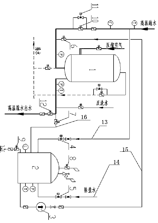
[0021] refer to figure 1 Shown is the temperature protection device of the filter element type high temperature iron removal filter 1 of the present invention. Including: a water tank 2, a first pipeline 13, a second pipeline 14, a third pipeline 15, a fourth pipeline 16, a hot water inlet valve arranged on the first pipeline 13, a desalinated water inlet valve arranged on the second pipeline 14 Water valve, the water pump 3 that is arranged on the 3rd pipeline 15 and the circulating water inlet valve, the water outlet valve that is arranged on the 4th pipeline 16, the first pipeline 13 connects the water inlet of water tank 2 to inject hot water to water tank 2, the second pipeline 14 is connected to the water inlet of the water tank 2 to inject demineralized water into the water tank 2. One end of the third pipe 15 is connected to the ...


PUM


Abstract

The invention discloses a protective device of a filter element type high-temperature iron removing filter. The protective device is characterized by comprising a water tank, a first pipeline, a second pipeline, a third pipeline, a fourth pipeline, a hot water inlet valve on the first pipeline, a demineralized water inlet valve on the second pipeline, a water pump and a circulating water inlet valve which are arranged on the third pipeline, and a water outlet valve on the fourth pipeline, wherein the first pipeline is connected with a water inlet of the water tank for injecting hot water into the water tank; the second pipeline is connected with the water inlet of the water tank for injecting demineralized water into the water tank; one end of the third pipeline is connected with a water outlet of the water tank, and the other end of the third pipeline is connected with a water inlet of the filter element type high-temperature iron removing filter; the fourth pipeline is connected with a water outlet of the filter element type high-temperature iron removing filter. The protective device disclosed by the invention ensures safety operation of an iron removing filter body and a filter element and prolongs the service life of the filter. Moreover, the protective device can satisfy backwashing requirements of filter elements which are made of different materials, and is wide in subject range.

Description

technical field [0001] The invention relates to a protection device for a filter, in particular to a protection device for protecting a filter element type high temperature iron removal filter by avoiding drastic temperature changes of the filter element type high temperature iron removal filter, and the invention belongs to the field of protection devices . Background technique [0002] Large-scale thermal power plants for external heating generally need to set up the first station of the heating network, which uses steam to heat the circulating water of the heating network, and the heated circulating water of the heating network supplies heat to the outside, and the steam condenses into water. Due to the corrosion of long-distance pipelines and heat exchangers, the hydrophobic water contains a large amount of iron oxides. The parameters of the heating network drainage vary with the steam parameters, but the general parameters of the heating network drainage are: temperatu...

Claims


Application Information

Patent Timeline
Patent Type & Authority Patents(China)
IPC IPC(8): B01D35/14
Inventor 吴怡卫游晓宏许玮韩松江蛟陈剑光王志斌高嘉梁龚国辉沙海伟蒋淡宁
Owner CEEC JIANGSU ELECTRIC POWER DESIGN INST
Why Eureka
Eureka Blog
Learn More