Automatic gap compensating bolt
A gap and bolt technology, which is applied in the field of gap self-compensating bolts, can solve problems such as easy aging of components, easy deformation of fastening surfaces, and safety accidents, so as to improve stability and safety, realize secondary fastening, and structure simple effect
- Summary
- Abstract
- Description
- Claims
- Application Information
AI Technical Summary
Problems solved by technology
Method used
Image

Examples
Embodiment 1
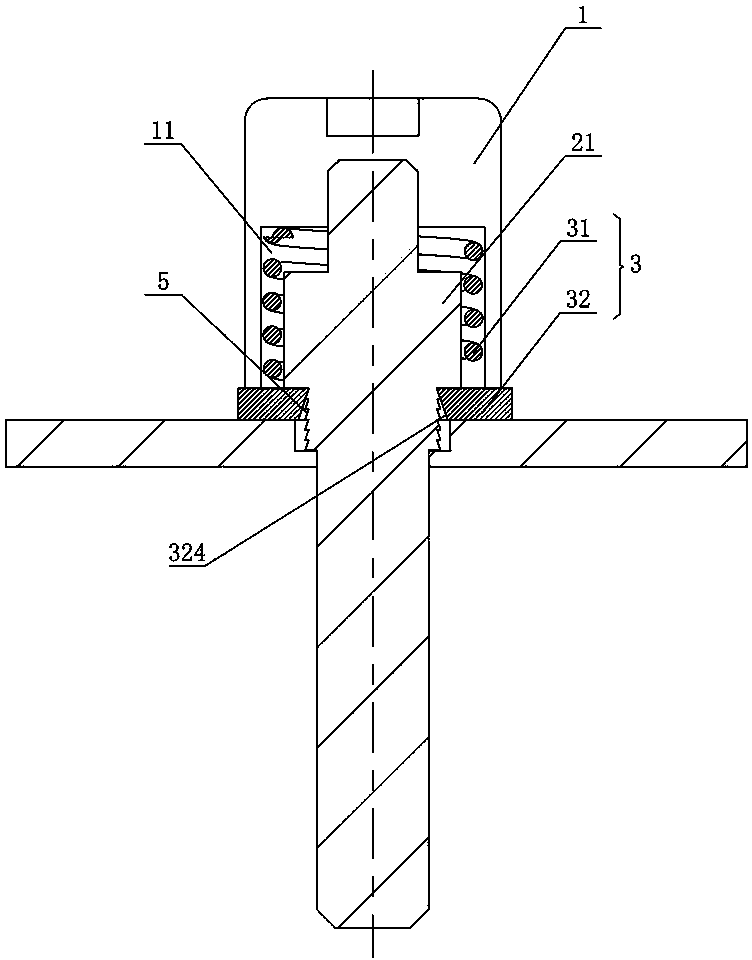
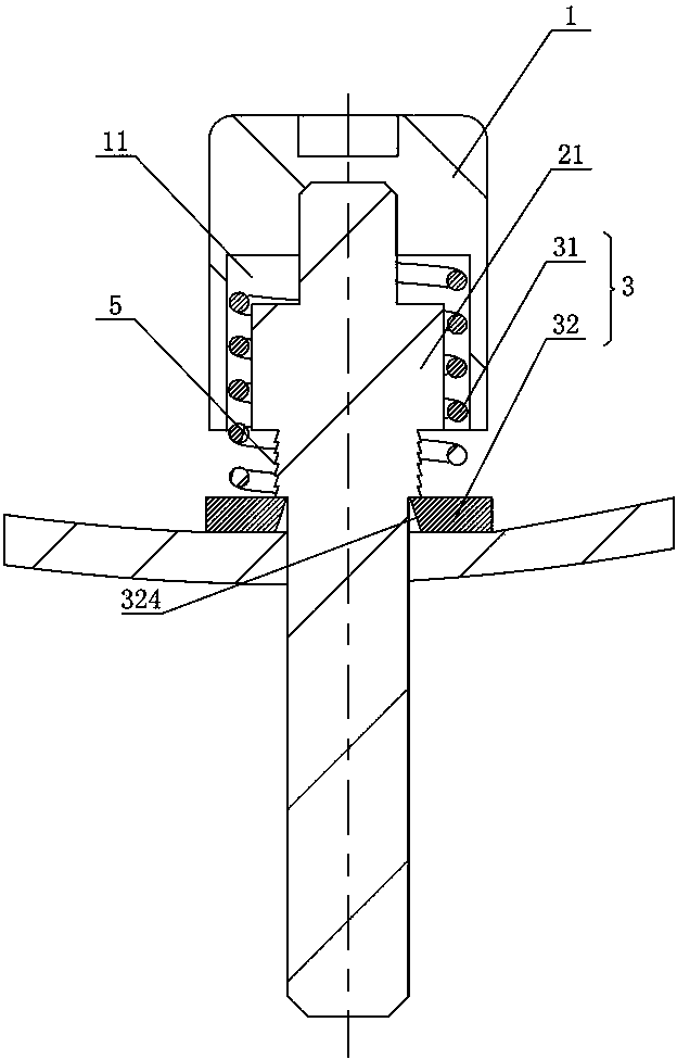
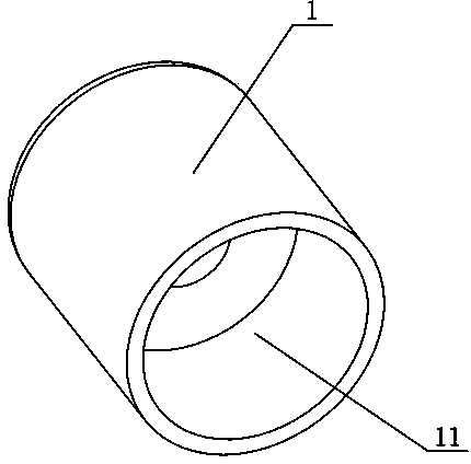
[0068] Figure 1 to Figure 6 It shows the first embodiment of the gap self-compensating bolt of the present invention. The bolt includes a nut 1 and a screw rod 2. After the screw rod 2 is screwed to the fastening surface, the nut 1 will directly press the fastening surface to achieve tightness. Solid connection, its structure is simple, easy to install, and a stroke chamber 11 is provided in the nut 1, the stroke chamber 11 is equipped with an elastic compensating device 3, that is, in the installed state, the elastic compensating device 3 will be in the stroke chamber 11 due to itself Internal deformation is generated to form a pre-release force. When there is a gap between the nut 1 and the fastening surface, the elastic compensating device 3 will restore the deformation and move to the fastening surface, and make up the gap between the nut 1 and the fastening surface , to ensure that the bolt structure will not loosen, realize the secondary fastening effect, and greatly im...
Embodiment 2
[0072] Figure 7 to Figure 14 It shows the second embodiment of the gap self-compensating bolt of the present invention. The bolt is basically the same as that of Embodiment 1, the only difference being that the screw rod 2 is provided with a heat insulating member 4, which can act as a bridge breaker. Thermal effect, its structure is simple, easy to install, one end of the elastic compensating device 3 is offset against the nut 1, and the other end is offset against the heat insulating element 4, that is, when the installed state, the elastic compensating device 3 will be in the stroke cavity 11 due to itself Deformation is generated to form a pre-release force. When the heat insulating part 4 fails and disappears, there will be a gap between the bolt structure and the fastening surface. The gap between the cap 1 and the fastening surface ensures that the bolt structure will not loosen, realizes the secondary fastening effect, and greatly improves the stability and safety of ...
Embodiment 3
[0082] Figure 15 to Figure 22It shows the third embodiment of the gap self-compensating bolt of the present invention, which is basically the same as that of Embodiment 1, the only difference is that the driving part 31 includes a driving spring 311, the compensating part 32 is an elastic snap ring, and the driving spring 311 is set on the On the screw 2, one end of the driving spring 311 is offset against the nut 1, and the other end is offset against the compensating piece 32. The screw 2 is provided with an anti-retraction boss 21, which is flush with the bottom end of the nut 1, and the compensating piece 32 It is sandwiched between the anti-retraction boss 21 and the heat insulator 4 and tightened around the periphery of the screw rod 2. The anti-retraction boss 21 is offset against the elastic snap ring to prevent the elastic snap ring from retreating when it is installed. Its structure Simple and reliable, the screw rod 2 is provided with at least two stages of feeding...
PUM
 Abstract
Description
Claims
Application Information
 - R&D
- Intellectual Property
- Life Sciences
- Materials
- Tech Scout
- Unparalleled Data Quality
- Higher Quality Content
- 60% Fewer Hallucinations
Browse by: Latest US Patents, China's latest patents, Technical Efficacy Thesaurus, Application Domain, Technology Topic, Popular Technical Reports.
© 2025 PatSnap. All rights reserved.Legal|Privacy policy|Modern Slavery Act Transparency Statement|Sitemap|About US| Contact US: help@patsnap.com