Rotation clamping device

A technology of clamping device and clamping sleeve, which is applied in the field of fixture tooling

Pending Publication Date: 2020-02-07
WENZHOU HANKON AUTO SENSOR
View PDF0 Cites 2 Cited by
  • Summary
  • Abstract
  • Description
  • Claims
  • Application Information

AI Technical Summary

Problems solved by technology

[0005] For those skilled in the art, how to design a rotary device that can automatically clamp and meet the large error when the manipulator picks and places the workpiece is a technical problem that needs to be solved at present.

Method used


Image

  • Rotation clamping device
  • Rotation clamping device
  • Rotation clamping device

Examples


Embodiment Construction

[0025] The core of the present invention is to provide a rotary clamping device, which realizes rapid clamping and loosening by laterally moving the expansion sleeve and the clamping sleeve, which can make the clamped workpiece rotate synchronously and automatically clamp. It can still be used when the workpiece has a large position error.

[0026] In order to enable those skilled in the art to better understand the technical solutions of the present invention, the rotary clamping device of the present invention will be described in detail below in conjunction with the accompanying drawings and specific implementation methods.

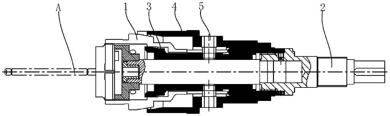
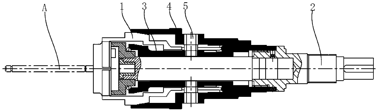
[0027] Such as Figure 1A with Figure 1B As shown, it is a structural schematic diagram of the collet 1, the rotating shaft 2, the expansion sleeve 3, and the clamping sleeve 4 in the rotary clamping device provided by the present invention. Figure 1A Indicates the released state, Figure 1B Indicates the clamping state, and A in the figure indicate...


PUM


Abstract

The invention discloses a rotation clamping device. At least three notches along the axis direction are arranged at the overhanging end of a flexible chuck so as to form multiple sectioning claws, andclamping and fixing are realized through relative converging and separating of the multiple sectioning claws; and a rotary shaft is driven by a drive device so as to rotate, the flexible chuck is synchronously driven to rotate, and a workpiece is further driven to rotate synchronously. An opening sleeve is arranged in the flexible chuck; a clamping sleeve is arranged on the outer part of the flexible chuck; the opening sleeve and the clamping sleeve are fixed relatively and are driven through a telescopic device so as to move along the axial direction; the opening sleeve and the clamping sleeve move synchronously along the axial direction; when the clamping sleeve moves outwards, the sectioning claws can be gradually extruded and converged, so that the workpiece is clamped; and when the opening sleeve moves inwards, the sectioning claws can be gradually opened, so that the workpiece is loosened. According to the rotation clamping device provided by the invention, through horizontallymoving the opening sleeve and the clamping sleeve, fast clamping and loosening are quickly realized, the clamped workpiece can be rotated synchronously, and the device can be used for automatically clamping and can be always used under the circumstance that a larger position error exists when a manipulator picks and places the workpiece.

Description

technical field [0001] The invention relates to the technical field of fixtures and tooling, and further relates to a rotary clamping device. Background technique [0002] When cutting, polishing, drilling and other operations on the workpiece, it is necessary to clamp and position the workpiece before processing, usually using a three-jaw clamp to achieve clamping; [0003] The spring collet clamping device is a kind of cylindrical fixture used to fix the drill bit or milling cutter on the milling machine. The spring collet clamping device can accurately locate and clamp the workpiece or tool, can resist torque and withstand cutting forces from multiple directions, realize quick release of the workpiece or tool, ensure machining accuracy and avoid damage to the workpiece, and can be used in a wide range The ability to work within the spindle speed range with only minimal loss of clamping force. [0004] In the field of automatic processing, the rotary processing parts or ...

Claims


Application Information

Patent Timeline
Patent Type & Authority Applications(China)
IPC IPC(8): B23B31/40
CPCB23B31/4006B23B31/402B23B31/4026
Inventor 薛肇江陈如意
Owner WENZHOU HANKON AUTO SENSOR
Why Eureka
Try Eureka