Objective table partition temperature control system for 3D printing

A temperature control system and 3D printing technology, applied in the field of 3D printing, can solve the problems of the machine not rising to the working temperature, the user waits for a long time, and the large working current, etc. Plug-in oxidation and ablation problem solving, high temperature control effect

Inactive Publication Date: 2014-07-23
UNIV OF SCI & TECH OF CHINA
View PDF5 Cites 12 Cited by
  • Summary
  • Abstract
  • Description
  • Claims
  • Application Information

AI Technical Summary

Problems solved by technology

[0002] The existing 3D printer stage mostly adopts the working mode of overall heating. When the system is working, the heating area is large, the heat dissipation area is large, the energy waste is serious, the temperature rises slowly, the user waits for a long time, and the machine with a long use time may even appear The user experience is poor if the temperature cannot reach the proper working temperature
And under the conventional design voltage (12V or 24V), in order to have enough heating electric power, a large working current is required, resulting in serious heating of the circuit, low safety and poor reliability

Method used


Image

  • Objective table partition temperature control system for 3D printing
  • Objective table partition temperature control system for 3D printing
  • Objective table partition temperature control system for 3D printing

Examples


Embodiment 1

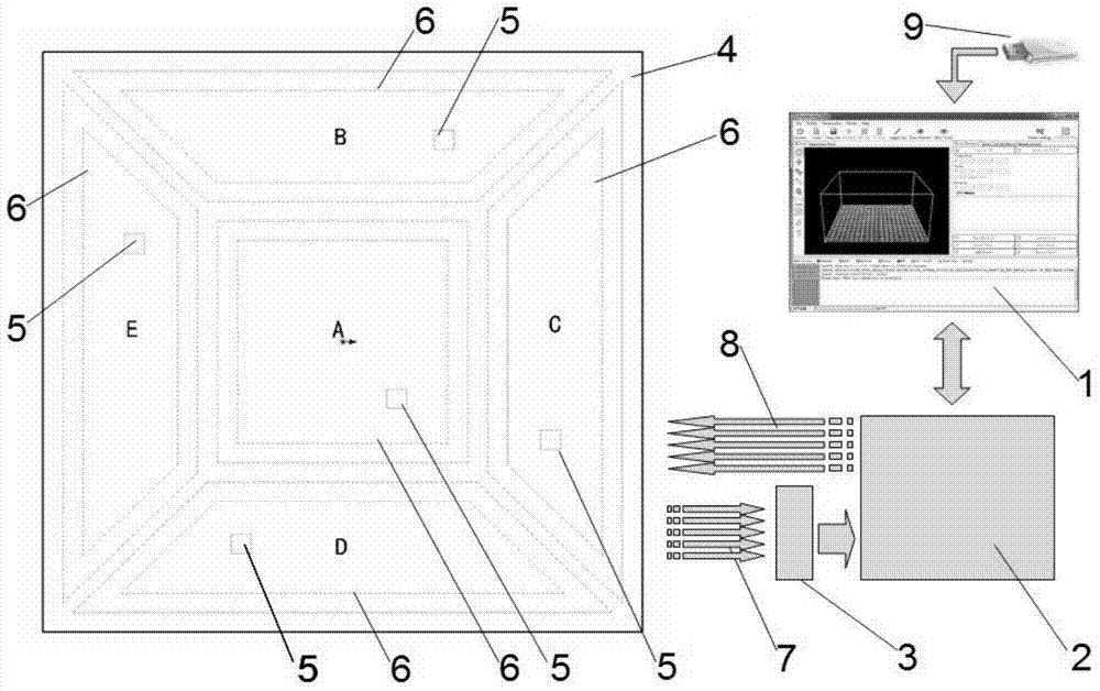
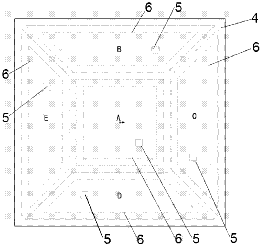
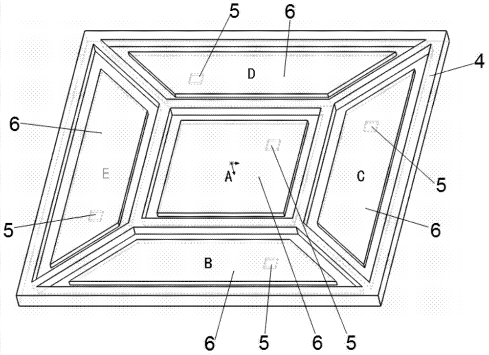
[0020] Such as figure 1 As shown in FIG. 1 , the schematic diagram of the temperature control system for the stage partitions of the present invention is also a schematic diagram of an implementation process of the present invention. Wherein, the stage 4 is divided into five partitions according to design requirements, respectively A, B, C, D, E, each partition is a temperature control unit, and each temperature control unit includes an independent temperature detection probe 5 and heating Device 6. After the host computer 1 reads the information of the user file 9, according to the size and position of the parts to be printed in the file, it can automatically or manually print in the five partitions A, B, C, D, and E of the stage 4. Assign work zones, and start the temperature detection and control of the corresponding work zones; the control circuit 2 obtains and recognizes instructions from the host computer 1, and outputs the signal to the heater 6 of the temperature cont...

Embodiment 2

[0027] Such as Figure 4 , Figure 5 As shown, the schematic diagram of the front of the stage and the top view of the bottom of the stage in Embodiment 2 of the present invention. In embodiment 2, when the size of the stage is relatively large, the stage is divided into 9 partitions of A, B, C, D, E, F, G, H, and I, and each partition is a temperature control zone. unit, the bottom of each partition is installed with an independent temperature detection probe 5 and a heater 6 to detect and control the temperature of the corresponding partition. The implementation process and implementation effect of Embodiment 2 are basically the same as Embodiment 1.

[0028] According to the size and shape of the stage, other partition schemes can also be carried out on the stage. The essence is to choose a suitable partition method for the stage of different sizes and shapes, and divide it into multiple temperature control units to realize It has the characteristics of fast heating spee...


PUM


Abstract

The invention provides an objective table partition temperature control system for 3D printing. The objective table partition temperature control system comprises an upper computer, a control circuit and a partition-type objective table. After the upper computer reads user file information, working partitions can be automatically or manually distributed according to the size and position of an object needing to be printed in a file, temperature detection and control over the corresponding partition are started, and multi-partition distribution and temperature control can also be achieved under the situation that a plurality of components are printed at the same time. The control circuit can identify instructions of the upper computer, complete temperature detection and control over the partitions, and upload data to the upper computer. The partition-type objective table is composed of a plurality of temperature control units. Each temperature control unit comprises an independent temperature probe and a heater. Compared with an existing objective table temperature control system, the objective table partition temperature control system has the advantages that the corresponding temperature control partitions can be automatically or manually started according to the sizes and the positions of the printed components, the heating speed is high, energy consumption is low, safety is high, and precision of temperature control is high.

Description

technical field [0001] The invention belongs to the technical field of 3D printing, and in particular relates to a stage partition temperature control system for 3D printing. Background technique [0002] The existing 3D printer stage mostly adopts the working mode of overall heating. When the system is working, the heating area is large, the heat dissipation area is large, the energy waste is serious, the temperature rises slowly, the user waits for a long time, and the machine with a long use time may even appear If the temperature cannot reach the proper working temperature, the user experience is poor. Moreover, under the conventional design voltage (12V or 24V), in order to have sufficient heating power, a relatively large operating current is required, resulting in severe heating of the circuit, low safety, and poor reliability. Contents of the invention [0003] The object of the present invention is to solve the problems in the prior art, and design a more efficie...

Claims


Application Information

Patent Timeline
Patent Type & Authority Applications(China)
IPC IPC(8): G05D23/20B29C67/00
Inventor 吴旭周江宁何海辉王黎丽刘雅静孙红娟
Owner UNIV OF SCI & TECH OF CHINA
Why Eureka
Try Eureka