Lighting Unit And Light Bar Having The Same

A technology for light-emitting units and light-emitting elements, which is applied to semiconductor devices, light sources, electric light sources, etc.

Inactive Publication Date: 2014-07-23
LEXTAR ELECTRONICS CORP
View PDF6 Cites 44 Cited by
  • Summary
  • Abstract
  • Description
  • Claims
  • Application Information

AI Technical Summary

Problems solved by technology

Generally speaking, in the automatically produced LED strips, the LEDs are soldered to the circuit board through the Surface Mount Technology (SMT) process, so a lot of process time will be consumed in the manufacture of the LED strips
[0004] In addition, when the LED light bar in the prior art is used for a long time, part of the LEDs may be damaged or the brightness will be attenuated. However, since the LEDs are welded on the circuit board, the LEDs are not easy to replace.
On the other hand, the light-emitting directions of the LED light bars in the prior art all face the same direction (ie, the direction facing away from the circuit board), so the light-emitting angle of the light-emitting diode light bars in the prior art will be limited.

Method used


Image

  • Lighting Unit And Light Bar Having The Same
  • Lighting Unit And Light Bar Having The Same
  • Lighting Unit And Light Bar Having The Same

Examples


Embodiment Construction

[0033] A number of implementations of the present invention will be disclosed below with the accompanying drawings. For the sake of clarity, many practical details will be described together in the following description. However, it should be understood that these practical details should not be used to limit the invention. That is, in some embodiments of the invention, these practical details are not necessary. In addition, for the sake of simplifying the drawings, some conventional structures and elements in the prior art will be shown in a simple and schematic manner in the drawings.

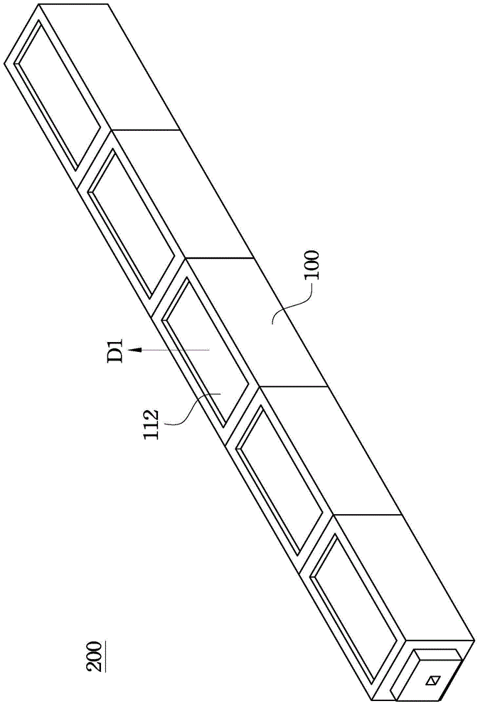
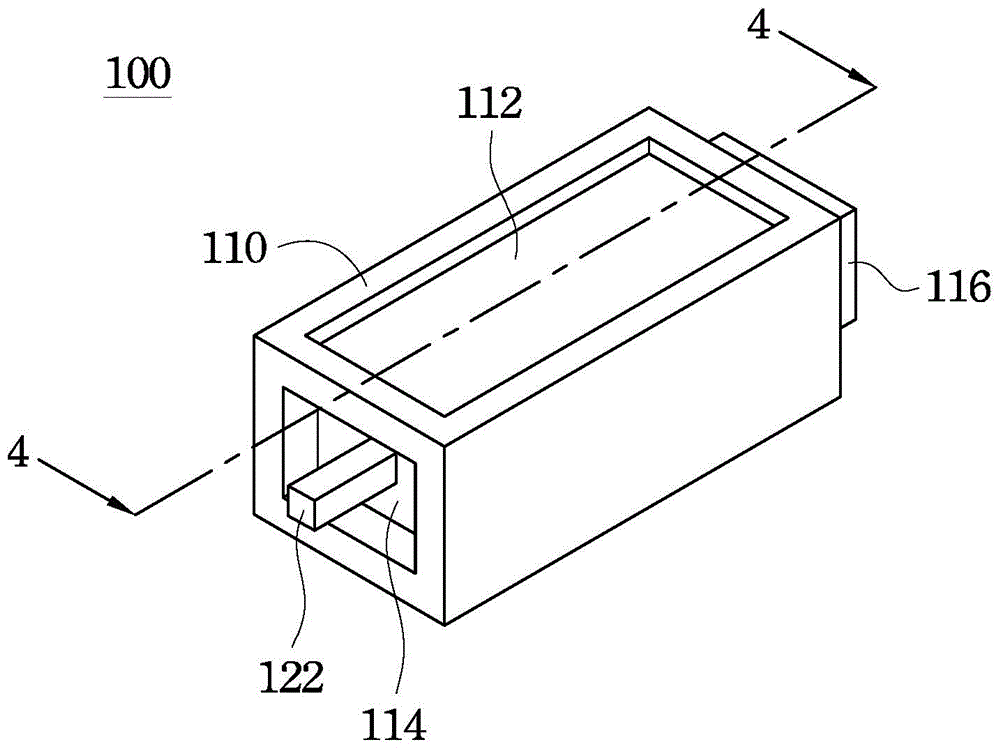
[0034] figure 1 A perspective view of a light emitting light bar 200 according to an embodiment of the present invention is shown. figure 2 draw figure 1 A perspective view of a light-emitting unit 100 in the light-emitting light bar 200 of FIG. see also figure 1 and figure 2 , the light emitting light bar 200 is formed by connecting N light emitting units 100 in series, wherein N is ...


PUM


Abstract

A lighting unit is provided and includes a cup body, a substrate, a first conductive wire connector and a second conductive wire connector. The cup body has a light emitting surface, a first end portion, and a second end portion. The substrate is located in the concave accommodating cavity of the cup body. A lighting element is located on the substrate, and has a light emitting direction toward the light emitting surface. The first and second conductive wire connectors are respectively located at two sides of the substrate in the accommodating cavity. A portion of the first conductive wire connector protrudes from the surface of the first end portion to form a first male connection terminal. The second conductive wire connector is recessed in the surface of the second end portion to form a first female connection terminal.

Description

technical field [0001] The invention relates to a light emitting unit and a light bar with the light emitting unit. Background technique [0002] A light-emitting diode (Light-Emitting Diode; LED) is a semiconductor element. In recent years, due to the progress of science and technology, light-emitting diodes can not only be used in indicator lights of electronic devices or light-emitting elements of display panels, but also have been widely used in thin TVs, computer monitors and daily lighting equipment. Light-emitting diodes have the advantages of long life, low power consumption, small size, shock resistance and wide application. [0003] The LED light bar in the prior art has LEDs and a circuit board. The manufacturing method of the light bar is to fix the light-emitting diodes on the circuit board by soldering, so the arrangement of the light-emitting diodes on the circuit board is limited by the circuit layout. Generally speaking, in the automatically produced LED ...

Claims


Application Information

Patent Timeline
Patent Type & Authority Applications(China)
IPC IPC(8): H01L33/48H01L33/62F21S4/00F21V21/002F21Y101/02
CPCF21K9/00F21S2/005F21Y2101/00F21Y2115/10H01L2224/48091H01L2224/48247H01L2924/00014
Inventor 秦仕杰
Owner LEXTAR ELECTRONICS CORP
Why Eureka
Try Eureka