Novel LED (light emitting diode) light source and bulb manufactured by using same

A technology of LED light source and LED chip, applied in the field of LED light source, can solve the problems of small light-emitting angle of the light source, poor heat dissipation effect of the light source, and poor insulation and withstand voltage characteristics of the substrate, so as to improve the uniformity and softness of the light output, and be widely popularized. Use value, the effect of good insulation and withstand voltage characteristics

Active Publication Date: 2013-02-06
XIAMEN HUALIAN ELECTRONICS CO LTD
View PDF6 Cites 7 Cited by
  • Summary
  • Abstract
  • Description
  • Claims
  • Application Information

AI Technical Summary

Problems solved by technology

[0002] Most of the existing LED light sources are formed by mounting LED chips on aluminum substrates, TOP brackets, copper substrates and other substrates. This kind of light source mainly has the following problems: 1. Because the substrate hinders the light transmission of the LED chip, As a result, the luminous angle of the light source is small, so that part of the light of the LED chip is lost, and the luminous efficiency of the light source is reduced; 2. The substrate hinders the heat dissipation of the LED chip, so that the heat dissipation effect of the overall light source is not good. It is necessary to consider the matching radiator, which not only limits the structural design of the lamp, but also increases the manufacturing cost of the lamp
3. The insulation and voltage resistance characteristics of the substrate are poor, which limits the choice of driving power supply, and ultimately leads to the large volume, high cost and low luminous efficiency of the manufactured lamps

Method used


Image

  • Novel LED (light emitting diode) light source and bulb manufactured by using same
  • Novel LED (light emitting diode) light source and bulb manufactured by using same
  • Novel LED (light emitting diode) light source and bulb manufactured by using same

Examples


Embodiment Construction

[0023] The present invention will be described in further detail below in conjunction with the accompanying drawings and specific embodiments.

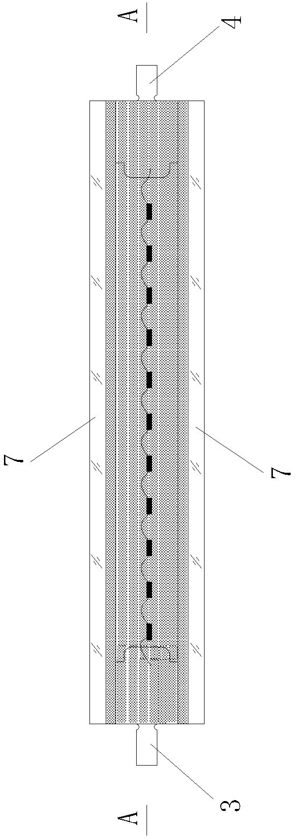
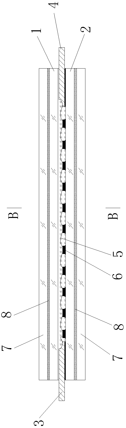
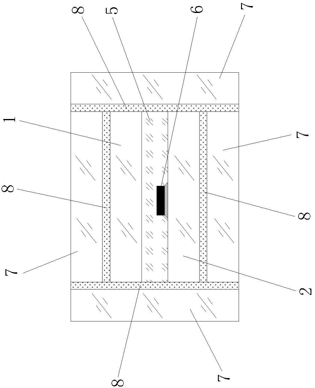
[0024] Figure 1 to Figure 3 As shown, a new type of LED light source includes an upper glass substrate 1, a lower glass substrate 2, two external electrodes 3, 4, and a plurality of LED chips 6 are packaged with transparent glue 5 between the upper and lower glass substrates 1, 2. , the two external electrodes 3, 4 protrude between the upper and lower glass substrates 1, 2 and respectively connect with the two electrodes formed by serial connection of multiple LED chips 6;

[0025] The upper surface of the upper glass substrate 1 and the lower surface of the lower glass substrate 2 are covered with a protective glass plate 7 , and a fluorescent material layer 8 is coated between the protective glass plate 7 and the upper surface of the upper glass substrate 1 and the lower surface of the lower glass substrate 2 .

[0026] The uppe...


PUM


Abstract

The invention discloses a novel LED (light emitting diode) light source and a bulb manufactured by using the light source. The LED light source comprises two upper and lower glass substrates and two exported electrodes, wherein one or more LED chips are packaged between the upper and lower glass substrates by using a scotch tape; when one LED chip is packaged, the two exported electrodes stretch between the upper and lower glass substrates to be receptively connected with two electrodes of the LED chip; when a plurality of LED chips are packaged, the two exported electrodes stretch between the upper and lower glass substrates to be respectively connected with the two electrodes which are formed by the LED chips which are serially connected or connected in parallel; glass protecting plates can be wrapped at the upper surface of an upper glass substrate, the lower surface of a lower glass substrate and side surfaces of the upper and lower glass substrates; and fluorescent material layers are coated at the upper surface of the upper glass substrate, the lower surface of the lower glass substrate and between the side surfaces of the upper and lower glass substrates. The LED light source is large in light emission angle, good in heat radiation effect and high in light emission efficiency.

Description

technical field [0001] The present invention relates to a novel LED light source, especially a novel LED light source, and also relates to an LED light bulb using the novel LED light source. Background technique [0002] Most of the existing LED light sources are formed by mounting LED chips on aluminum substrates, TOP brackets, copper substrates and other substrates. This kind of light source mainly has the following problems: 1. Due to the obstruction of the substrate to the light transmission of the LED chip, As a result, the luminous angle of the light source is small, so that part of the light of the LED chip is lost, and the luminous efficiency of the light source is reduced; 2. The substrate hinders the heat dissipation of the LED chip, so that the heat dissipation effect of the overall light source is not good. It is necessary to consider the matching radiator, which not only limits the structural design of the lamp, but also increases the manufacturing cost of the l...

Claims


Application Information

Patent Timeline
Patent Type & Authority Applications(China)
IPC IPC(8): F21S2/00F21V9/10F21V29/00F21Y101/02F21K9/23F21V9/40F21V29/503F21Y115/10
Inventor 林祯祥李小红柴储芬
Owner XIAMEN HUALIAN ELECTRONICS CO LTD
Why Eureka
Try Eureka