Parts mounting device and parts mounting method

A technology for mounting devices and components, applied in the direction of electrical components, electrical components, etc., can solve the problems of inability to achieve installation, electronic components do not fall, difficult to absorb electronic components, etc., to achieve the effect of improving productivity

Active Publication Date: 2018-05-01
JUKI CORP
View PDF6 Cites 0 Cited by
  • Summary
  • Abstract
  • Description
  • Claims
  • Application Information

AI Technical Summary

Problems solved by technology

Among the shielding cases, there are shielding cases whose wall thickness is reduced for weight reduction, and if only one part of the electronic component is attracted as shown in the above-mentioned component mounting device, stable mounting cannot be achieved.
There is also a suction nozzle having a plurality of separate suction ports, but since the orientation of the suction nozzle is fixed regardless of the shape of the component in the above-mentioned component mounting apparatus, it is difficult to properly suction the separated part of the electronic component. Adsorption site
[0007] In addition, the recognition range of electronic parts by laser light or image recognition is limited, and there may be cases where electronic parts do not fall within the recognition range
In this case, there is a problem in the component mounting apparatus that the electronic component picked up by the suction nozzle cannot be recognized, and the electronic component cannot be mounted on the board.

Method used


Image

  • Parts mounting device and parts mounting method
  • Parts mounting device and parts mounting method
  • Parts mounting device and parts mounting method

Examples


Embodiment Construction

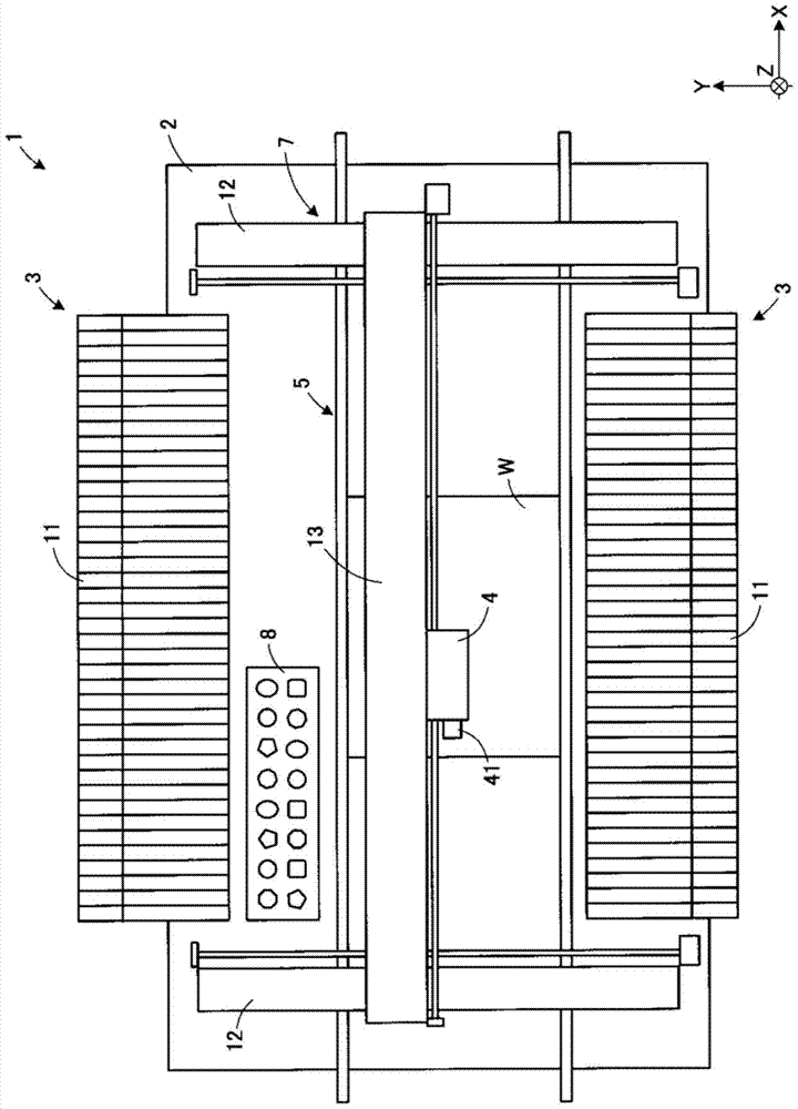
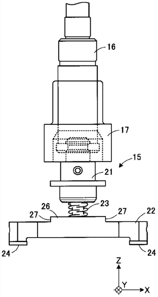
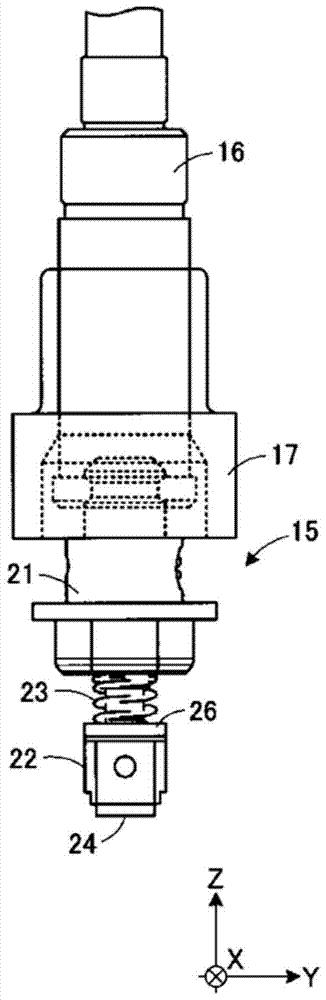
[0052] Below, refer to Figure 1 to Figure 5 , the first embodiment of the present invention will be described in detail. figure 1 It is a schematic plan view of the component mounting device according to the first embodiment. Fig. 2 is a plan view of the suction nozzle according to the first embodiment. image 3 It is a control block diagram of the component mounting device according to the first embodiment. In addition, although the case where the component mounting apparatus of this invention is used for mounting a shield case on a board|substrate is demonstrated below, it is not limited to this structure. The component mounting device of the present invention can also be used when mounting other electronic components.

[0053] Such as figure 1As shown, the component mounting apparatus 1 is configured to mount an electronic component 58 (see FIG. 4 ) supplied from a component feeder 3 serving as a component supply device onto a substrate W by using the mounting head 4 ....


PUM


Abstract

The invention provides a component mounting device and a component mounting method. The component mounting device properly mounts electronic components on a substrate irrelatively to the sizes and shapes of the electronic components. The component mounting device (1) utilizes a sucking nozzle (15) for sucking an electronic component (58). The electronic component is mounted on the substrate (W). Before the sucking nozzle sucks the electronic component, the orientation of the sucking nozzle is identified. Based on the identified orientation of the sucking nozzle, the sucking nozzle is rotated for a random angle. The front end of the sucking nozzle is provided with a plurality of sucking openings (25) which correspond with a plurality of sucking parts (59) that are preset on the electronic component for adjusting orientation of the sucking nozzle.

Description

technical field [0001] The present invention relates to a component mounting device and a component mounting method, which utilize suction [0002] The suction nozzle sucks the electronic component supplied from the component supply device, and mounts it on the board. Background technique [0003] Conventionally, as such a component mounting apparatus, there is known a technique of correcting the suction position and orientation of an electronic component suctioned by a suction nozzle and mounting it on a substrate (see Patent Documents 1 and 2). In the component mounting apparatus described in Patent Document 1, a light emitting unit and a light receiving unit are provided on a mounting head with suction nozzles interposed therebetween. Laser light is irradiated to the side of the electronic component held on the suction nozzle, and the orientation and mounting position of the electronic component on the board are corrected based on the shadow of the electronic component g...

Claims


Application Information

Patent Timeline
Patent Type & Authority Patents(China)
IPC IPC(8): H05K13/04
Inventor 赤川利也龟谷恭平野尻信明佐藤瑞穗
Owner JUKI CORP
Why Eureka
Try Eureka